
Propeller power device and ship

A power device and propeller technology, which is applied in the direction of rotating propellers, ship propulsion, ship parts, etc., can solve the problems of high energy consumption, slow ship speed, poor seakeeping performance, etc., achieve high driving speed, optimize seakeeping performance, and reduce wave making The effect of resistance

Pending Publication Date: 2021-08-31
刘志刚
View PDF0 Cites 1 Cited by
  • Summary
  • Abstract
  • Description
  • Claims
  • Application Information

AI Technical Summary

Problems solved by technology

[0006] The purpose of the present invention is to provide a propeller power device and a ship to solve the technical problems of slow ship speed, poor seakeeping performance and high energy consumption in the prior art

Method used


Image

  • Propeller power device and ship
  • Propeller power device and ship
  • Propeller power device and ship

Examples


Embodiment 1

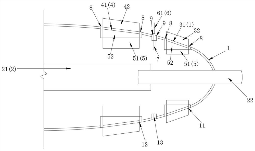
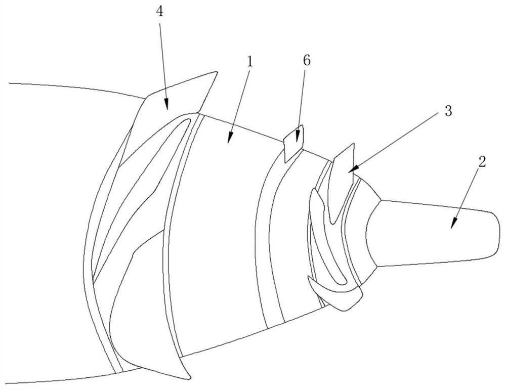
[0035] refer to figure 1 and image 3 , this embodiment mentions a propeller power device, including a casing 1, a front end protection structure 2, a first propeller assembly 3, a second propeller assembly 4 and a first drive structure 5, the casing 1 is connected to the bow, preferably arranged at The bow of the general rear drive type displacement ship or the parts below the waterline of the front bow of the catamaran, multihull, small waterplane area catamaran and other ships, and the rear drive device form a double drive with front and rear drive Force structure, shell 1 is streamlined design and its front end cross-sectional area is smaller than rear end cross-sectional area;

[0036] The front-end protection structure 2 passes through the front end of the casing 1 and is located outside the casing 1. The front-end protection structure 2 can absorb most of the energy generated by the impact of the front end of the propeller power unit, thereby weakening the impact force...

Embodiment 2

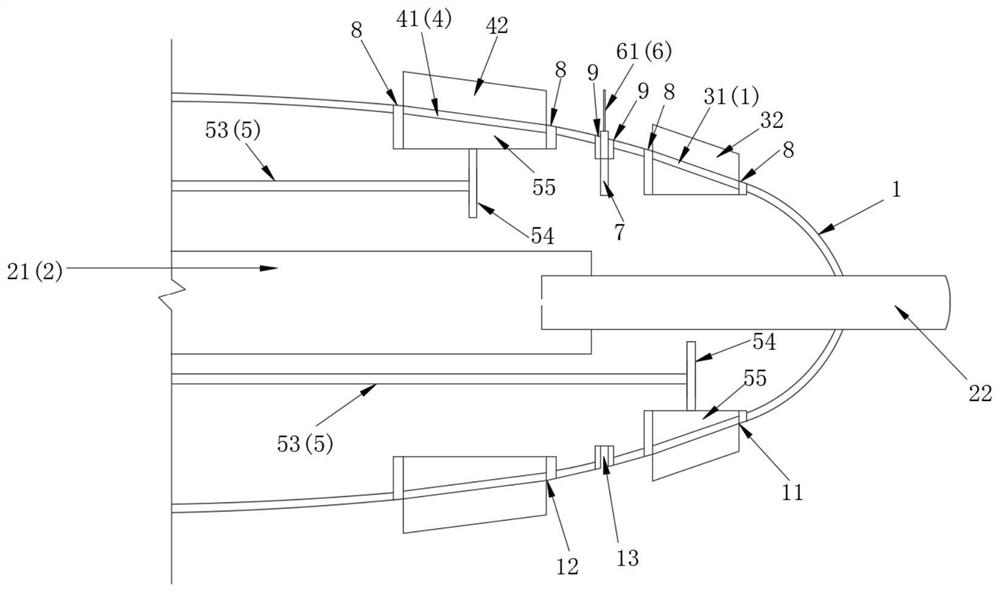
[0047] refer to figure 2 and image 3 , this embodiment mentions a propeller power device, including a casing 1, a front end protection structure 2, a first propeller assembly 3, a second propeller assembly 4 and a first drive structure 5, the casing 1 is connected to the bow, preferably arranged at The bow of the general rear drive type displacement ship or the parts below the waterline of the front bow of the catamaran, multihull, small waterplane area catamaran and other ships, and the rear drive device form a double drive with front and rear drive Force structure, shell 1 is streamlined design and its front end cross-sectional area is smaller than rear end cross-sectional area;

[0048] The front-end protection structure 2 passes through the front end of the casing 1 and is located outside the casing 1. The front-end protection structure 2 can absorb most of the energy generated by the impact of the front end of the propeller power unit, thereby weakening the impact forc...


PUM


Abstract

The invention provides a propeller power device and a ship, and relates to the technical field of ships. A temperature probe comprises a shell, a front end protection structure, a first propeller assembly, a second propeller assembly and a first driving structure, the shell is connected to the bow part, and the front end protection structure penetrates out of the front end of the shell and is located outside the shell; the first propeller assemblies and the second propeller assemblies are arranged on the shell and are in driving connection with the first driving structures correspondingly, and the two first driving structures drive the corresponding first propeller assemblies or the second propeller assemblies to be started at the same time after being started. By rotating, stirring, pumping, guiding and pushing the propellers, water in front of the propeller power device is attracted, dredged and shunted to the two sides and the lower rear portion of the ship, accumulation, superposition and blockage of the water under the collision and extrusion action of the bow are reduced, the wave-making resistance of the bow of the ship is greatly reduced, and the effects of saving more energy and being higher in running speed are achieved for the ship.

Description

technical field [0001] The invention relates to the technical field of ships, in particular to a propeller power device and a ship. Background technique [0002] At this stage, the common displacement ships on the market all use the rear drive mode to navigate, that is, relying on the power device installed at the stern of the ship to push the hull to collide with the bow and squeeze the water in front of it to discharge the space, so that the ship can go ahead. At the same time, the bow will also be subjected to the reaction resistance of the water body. This kind of resistance formed by the propelling, collision, and squeezing of the water body by the bow makes the water body superimpose and accumulate to generate waves, which is collectively called the bow wave-making resistance. [0003] The applicant has found that there are at least the following technical problems in the prior art: firstly, the faster the speed of the ship propulsion, the greater the bow wave resista...

Claims


Application Information

Patent Timeline
Patent Type & Authority Applications(China)
IPC IPC(8): B63H1/14B63H5/08
CPCB63H1/14B63H5/08
Inventor 刘志刚
Owner 刘志刚
Learn More