Re-wiring layer structure and preparation method thereof, and packaging structure and preparation method thereof
A technology of rewiring layer and packaging structure, applied in the field of semiconductor packaging, can solve problems such as complex process
- Summary
- Abstract
- Description
- Claims
- Application Information
AI Technical Summary
Problems solved by technology
Method used
Image
Examples
Embodiment 1
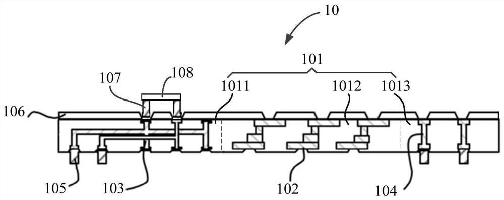
[0087] see figure 1 , this embodiment provides a redistribution layer structure 10, which is arranged between two adjacent chips, the redistribution layer structure 10 includes: a first insulating layer 101, a plurality of first connectors 102, a plurality of second The connecting piece 103 , the multiple third connecting pieces 104 , the multiple fourth connecting pieces 105 , the second insulating layer 106 , the fifth connecting piece 107 and the bypass capacitor 108 .
[0088] The first insulating layer 101 includes a first sub-insulating layer 1011 , and a second sub-insulating layer 1012 and a third sub-insulating layer 1013 arranged side by side with the first sub-insulating layer 1011 .
[0089] Wherein, the second sub-insulation layer 1012 and the third sub-insulation layer 1013 may be respectively located on two sides of the first sub-insulation layer 1011 .
[0090] The material of the first sub-insulation layer 1011 includes silicon insulation materials, including...
Embodiment 2
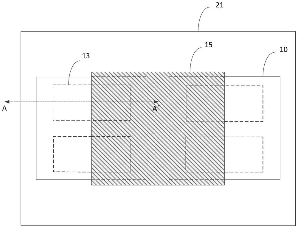
[0107] see image 3 with 4 , the present embodiment provides a packaging structure, including: a redistribution layer structure 10, a first micro-bump 12, a second micro-bump 14, a first chip 13, a second chip 15, a first packaging layer 16, a sixth Connector 17 , seventh connector 18 , third micro-bump 19 , fourth micro-bump 20 , package substrate 21 and second package layer 22 .
[0108] It should be noted that, in order to image 3 The shapes and positions of the redistribution layer structure 10, the first chip 13, the second chip 15 and the packaging substrate 21 are clearly shown in the figure, so image 3 The first micro-bump 12, the second micro-bump 14, the first encapsulation layer 16, the sixth connector 17, the seventh connector 18, the third micro-bump 19, and the fourth micro-bump 20 are not shown in and the second encapsulation layer 22 . but combine Figure 4 It can be understood that the first micro-bump 12, the second micro-bump 14, the first encapsulati...
Embodiment 3
[0130] On the basis of the first embodiment, this embodiment provides a method for preparing the redistribution layer structure 10 .
[0131] Figure 5 It is a schematic flowchart of a method for preparing the redistribution layer structure 10 shown in the embodiment of the present application.
[0132] Such as Figure 5 As shown, the preparation method of the redistribution layer structure 10 of this embodiment includes the following steps:
[0133] Step S110 : providing a temporary substrate 23 .
[0134] Wherein, the material of the temporary substrate 23 may be glass or silicon.
[0135]Step S120 : forming a third insulating layer 24 on the temporary substrate 23 .
[0136] Wherein, the material of the third insulating layer 24 is an adhesive material, which can be used to remove the temporary substrate 23 later.
[0137] Step S130 : forming the first insulating layer 101 on the third insulating layer 24 .
[0138] The first insulating layer 101 includes a first sub-...
PUM
 Abstract
Description
Claims
Application Information
 - R&D
- Intellectual Property
- Life Sciences
- Materials
- Tech Scout
- Unparalleled Data Quality
- Higher Quality Content
- 60% Fewer Hallucinations
Browse by: Latest US Patents, China's latest patents, Technical Efficacy Thesaurus, Application Domain, Technology Topic, Popular Technical Reports.
© 2025 PatSnap. All rights reserved.Legal|Privacy policy|Modern Slavery Act Transparency Statement|Sitemap|About US| Contact US: help@patsnap.com


