Detection equipment based on visual detection system and use method

A technology of visual inspection and inspection equipment, applied in the field of visual inspection, which can solve the problems of affecting detection efficiency, long cycle, and many turnover steps, and achieve the effects of avoiding air suction, less turnover steps, and high degree of automation

Active Publication Date: 2021-09-03
荣旗工业科技(苏州)股份有限公司
View PDF5 Cites 6 Cited by
  • Summary
  • Abstract
  • Description
  • Claims
  • Application Information

AI Technical Summary

Problems solved by technology

There are many turnover steps in the detection, which affects the detection efficiency; the comprehensive detection result of the material takes a long time, and it is impossible to realize the detection of all detection items of the material through a continuous detection process

Method used


Image

  • Detection equipment based on visual detection system and use method
  • Detection equipment based on visual detection system and use method
  • Detection equipment based on visual detection system and use method

Examples


Embodiment 1

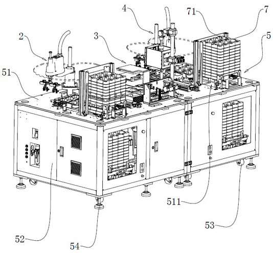
[0061] The embodiment of the present application discloses a detection device based on a visual detection system, which is used to take out the materials in the tray 7 for visual inspection, and then put them into the empty tray 7 . refer to figure 1 , in this embodiment, the tray 7 is a square plate body, which has six troughs 71 and is arranged in 2×3. Fifty pieces of materials can be stacked horizontally in each hopper 71 .

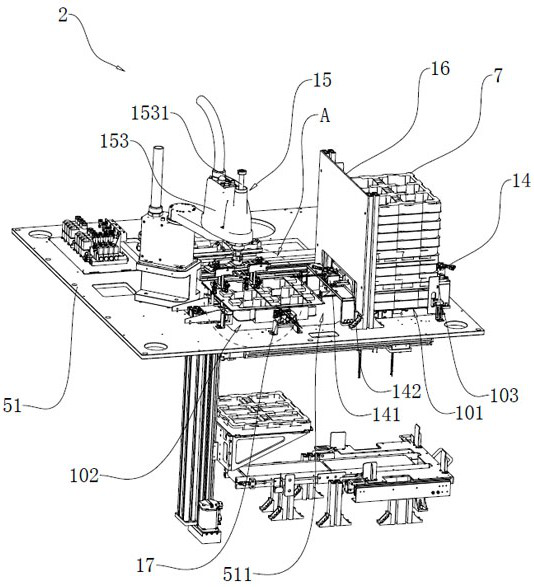
[0062] refer to figure 1 , the inspection equipment based on the visual inspection system includes a feeding area 2 , an inspection area 3 , a receiving area 4 and a workbench 5 . Wherein, the worktable 5 includes a worktable 51 , a table body 52 , universal wheels 53 and supporting feet 54 . Specifically, there is a component placement space inside the table body 52 , and the universal wheel 53 and the supporting feet 54 are installed under the table body 52 . The setting of universal wheel 53 facilitates the movement of the testing equipment; the...

Embodiment 2

[0111] The embodiment of the present application discloses a detection device based on a vision detection system and a method for using it. This embodiment is basically the same as Embodiment 1, except that the structure of the linear drive member 13 is changed.

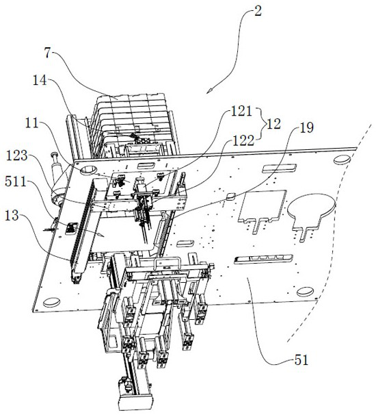
[0112] refer to Figure 11 , in the implementation of this embodiment, the linear drive member 13 is a driving cylinder, and is installed on the lower surface of the worktable 51; the telescopic direction of the piston rod of the driving cylinder is parallel to the length direction of the opening 511, and the piston rod and the connection Board 123 is connected. Simultaneously, on the lower surface of the worktable 51, a slide rail 19 (with a slider) is respectively installed outside the long sides of the opening 511; Parallel; both slide rails 19 extend from one end of the opening 511 to the other end. Both ends of the connecting plate 123 are installed on the sliders of the two slide rails 19 respectively. The ...

Embodiment 3

[0115] The embodiment of the present application discloses a detection device based on a vision detection system and a method for using it. This embodiment is basically the same as Embodiment 1, except that the structures of the tray supporting mechanism 14 and the tray fixing mechanism 17 are changed.

[0116] refer to Figure 12 and Figure 13 , in the implementation of this embodiment, the tray support mechanism 14 includes a first driving cylinder 141 and a first vacuum chuck 143 . The suction cup surface of the first vacuum suction cup 143 faces the palletizing position 101 , and the other side is affixed to the piston rod of the first driving cylinder 141 . During operation, the first driving cylinder 141 drives the first vacuum chuck 143 close to the side of the tray 7; through the vacuum adsorption of the first vacuum chuck 143 and the clamping effect of the two first vacuum chucks 143 on the tray 7, the support for the tray 7 is realized. .

[0117] Similarly, the...


PUM


Abstract

The invention relates to the field of visual detection, in particular to detection equipment based on a visual detection system and a use method. The detection equipment based on the visual detection system comprises a working table plate, and a feeding area, a detection area and a receiving area which are arranged on the working table plate, and the feeding area and the receiving area are each provided with a bearing piece, an up-down driving piece, a linear driving piece, a tray supporting mechanism and a mechanical arm. The detection area is provided with a carrying mechanism, a first detection mechanism, a second detection mechanism, a third detection mechanism, a first transfer mechanism and a second transfer mechanism. The use method of the detection equipment based on the visual detection system comprises the steps of feeding, detecting and receiving. Through the arrangement of the feeding area, the detection area and the material receiving area, detection of all detection items of materials can be completed through a one-time continuous detection process; and comprehensive detection results of the materials can be quickly obtained, and unqualified materials can be screened out. During detection, the automation degree is high, circulation steps are few, and the detection efficiency can be improved.

Description

technical field [0001] The present application relates to the field of visual detection, in particular to a detection device based on a visual detection system and a method for using it. Background technique [0002] In the field of electronic digital, due to the requirement of miniaturization, lamellar devices with coils and thin films are often used. This type of sheet-layer device includes two layers of film and a coil sandwiched between them; wherein, the film is made of elastic transparent plastic, and the two layers of film are connected by adhesive colloid. Due to the transparent nature of the film, the coil and colloid sandwiched between the two films can be observed from the outside. [0003] The inspection items of this type of sheet-layer devices usually include whether the size and contour are accurate, whether there is no waste (waste discharge refers to the removal of the waste adhered to the edge of the sheet-layer device when cutting), and whether there is l...

Claims


Application Information

Patent Timeline
Patent Type & Authority Applications(China)
IPC IPC(8): B07C5/00B07C5/04B07C5/02B07C5/36B07C5/38
CPCB07C5/00B07C5/04B07C5/02B07C5/362B07C5/38B07C2501/0063
Inventor 罗时帅钱根柳洪哲朱文兵钱曙光汪炉生陶磊蒋朝伟赵读伟金元元
Owner 荣旗工业科技(苏州)股份有限公司
Why Eureka
Try Eureka