Precise electrolytic machining process for blade profile

A processing technology and precision machining technology, which is applied in the field of precision electrolytic machining of blade profiles, can solve the problems of turbulent flow field, small radius of curvature of blades, and difference in quality of processed blades, and achieves weight reduction and airflow loss. Excellent processing quality

Active Publication Date: 2021-09-03
JIANGSU JIANGHANGZHI AIRCRAFT ENGINE COMPONENTS RES INST CO LTD
View PDF6 Cites 3 Cited by
  • Summary
  • Abstract
  • Description
  • Claims
  • Application Information

AI Technical Summary

Problems solved by technology

[0003] However, for the precision electrolytic processing technology used in the existing technology, our company has found that there are still some disadvantages in the long-term use process: 1. The electrolyte is rushed from bottom to top between the electrodes of the cathode tool, and the two parts that do not fit together The flow is diverted and discharged laterally in the gap of the side edge plate area, resulting in relatively turbulent flow fields at the leading edge and trailing edge of the blade during precision machining of small gaps, and the radius of curvature of the leading edge and trailing edge of the blade is relatively small, and the two cathode tools At the point where the electrodes are closest to each other, there is still a linear unfinished area on the leading edge of the blade; 2. Each independent blade on the integral impeller placed in the opposite direction is precisely processed one by one, the processing efficiency is extremely slow, and once the rotation process exists Small size changes will lead to differences in the quality of the corresponding processed blades on the overall impeller

Method used


Image

  • Precise electrolytic machining process for blade profile
  • Precise electrolytic machining process for blade profile
  • Precise electrolytic machining process for blade profile

Examples


Embodiment Construction

[0029] In order to make the technical means, creative features, goals and effects achieved by the present invention easy to understand, the present invention will be further described below in conjunction with specific embodiments.

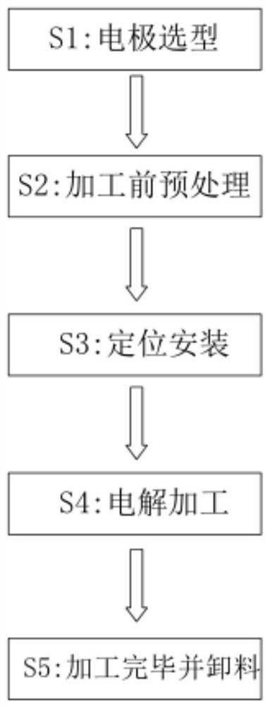
[0030] Such as Figure 1 to Figure 7 As shown, a precision electrolytic machining process for a blade profile includes the following steps:

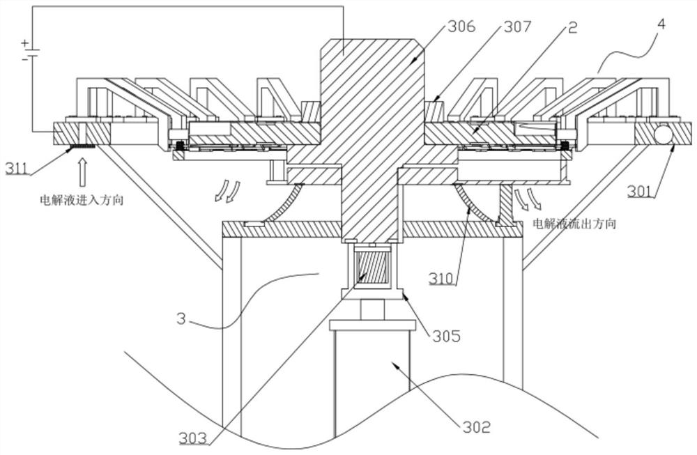
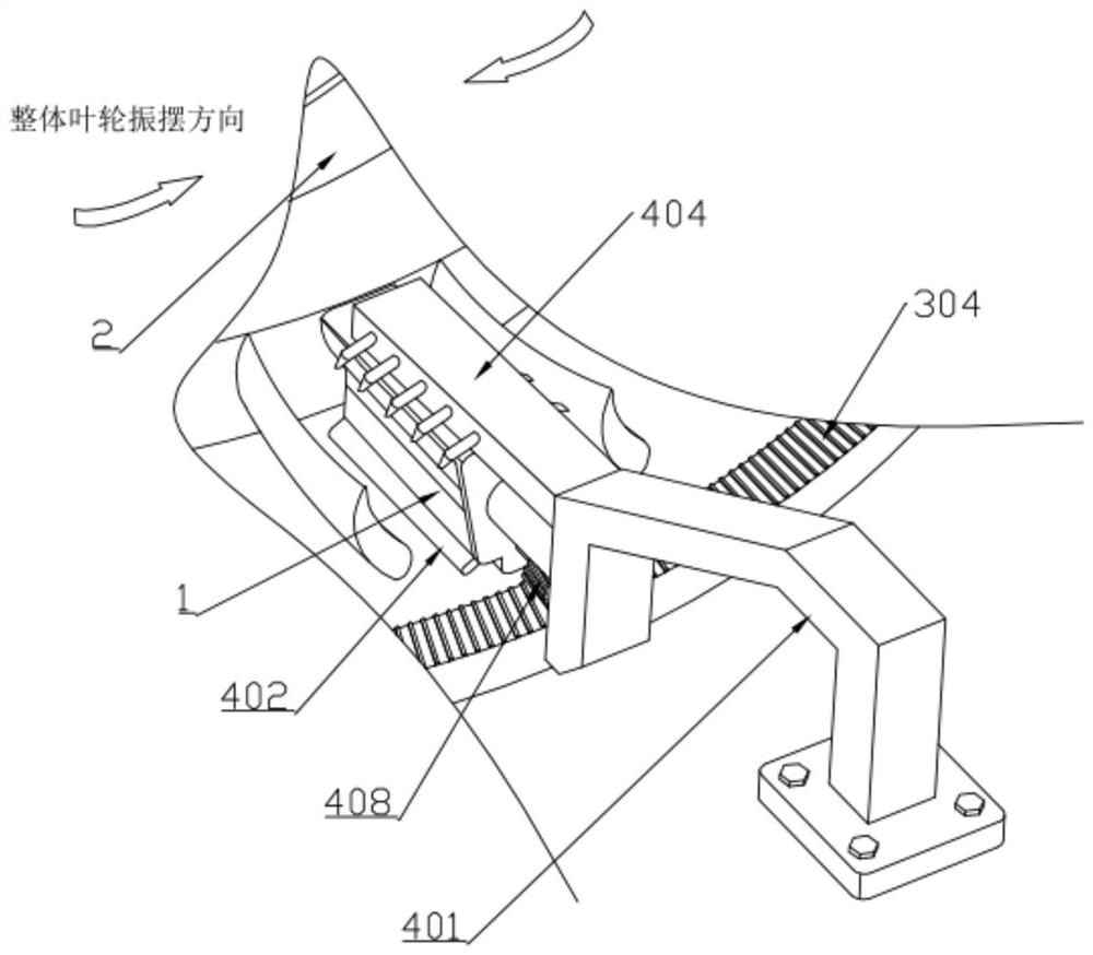
[0031] S1: Electrode type selection: According to the profile of the blade on the integral impeller 2 to be precisely processed, select the tool cathode 1, and the two sides of the tool cathode 1 are respectively offset from the blade pot and the blade back of the blade by the same amount;

[0032] S2: preprocessing before processing: check whether there are protrusions or depressions on the surface of the variable-section blade of the integral impeller 2, and use absolute ethanol to clean the variable-section blade and the tool cathode 1 respectively for the first time after the inspection;

[0033] S3: Po...


PUM


Abstract

The invention discloses a precise electrolytic machining process for a blade profile, and relates to the technical field of electrolytic machining. The process comprises the following steps of electrode type selection, pretreatment before machining, positioning installation, electrolytic machining and discharging after machining is finished. According to the process, a plurality of uniformly distributed follow-up mechanisms are arranged on a swing mechanism, and a blade basin part of a blade at one side and a blade back part of the other blade on two adjacent blades on an integral impeller are processed jointly by a tool cathode and a front edge cathode I and a front edge cathode II which are arranged in the tool cathode, a flow field is stable, the front edges of all the blades on the integral impeller are subjected to covering type electrolytic machining while short-circuit ablation is prevented, and the blade machining quality is guaranteed; and intermittent vibration electrolysis is carried out on the integral impeller which is horizontally placed, precise electrolytic machining of all blades on the integral impeller is synchronously completed within the rotating angle between blade channels, the precise electrolytic machining efficiency is greatly improved, and meanwhile the quality difference of the machined blades can be eliminated.

Description

technical field [0001] The invention relates to the technical field of electrolytic machining, in particular to a precision electrolytic machining process for blade profiles. Background technique [0002] In aero-engines, in order to achieve high-performance requirements such as weight reduction and airflow loss reduction, the integral impeller has now become a necessary structure for engines with a high thrust-to-weight ratio, and has been widely used in military and civil aero-engines. The cross-sectional changes are complex, which puts forward extremely high requirements on the processing and manufacturing technology. The existing technology usually uses stick-shaped electrodes to roughly machine the blank of the overall impeller to achieve a shape close to the final shape, and then through non-contact, loss-free cathode, Precision electrolysis with excellent processing quality is used for further processing, that is, two vibrating cathode tool electrodes set opposite eac...

Claims


Application Information

Patent Timeline
Patent Type & Authority Applications(China)
IPC IPC(8): B23H3/00B23H3/04B23H3/10B23H11/00
CPCB23H3/00B23H3/04B23H11/00B23H11/003B23H3/10
Inventor 吴江严小琳曹春晓
Owner JIANGSU JIANGHANGZHI AIRCRAFT ENGINE COMPONENTS RES INST CO LTD
Why Eureka
Try Eureka