Long-arm-span mechanical arm joint in large-magnetic-field high-vacuum strong-radiation environment

A radiation environment and high vacuum technology, applied in the direction of manipulators, manufacturing tools, joints, etc., can solve the problems of open joints where radioactive substances are easy to reside, radiation pollutants are easy to reside, and the angle range is limited, achieving smooth and regular surfaces. Increase the range of activities and reduce the effect of staying

Active Publication Date: 2021-09-03
SOUTHWESTERN INST OF PHYSICS
View PDF10 Cites 0 Cited by
  • Summary
  • Abstract
  • Description
  • Claims
  • Application Information

AI Technical Summary

Problems solved by technology

The vertical rotation uses a four-bar linkage mechanism, and the horizontal rotation uses a pulley pulley mechanism, which is applied to the European Tore Supra device. The movement range of the AIA robotic arm joints in the up and down direction is ±45°, left and right is ±90°, and the angle range The limited, barrel-shaped interior of the connecting rod is very prone to resident radiation contaminants and is not easy to clean
[0006]Open joints are prone to resident radioactive substances; the drive is directly limited by the space at the joint, and it is often difficult to increase the torque; although closed joints are not easy to resident radioactive pollutants, but The rotation range of a rotating shaft is difficult to exceed ±90°

Method used


Image

  • Long-arm-span mechanical arm joint in large-magnetic-field high-vacuum strong-radiation environment
  • Long-arm-span mechanical arm joint in large-magnetic-field high-vacuum strong-radiation environment
  • Long-arm-span mechanical arm joint in large-magnetic-field high-vacuum strong-radiation environment

Examples


Embodiment 1

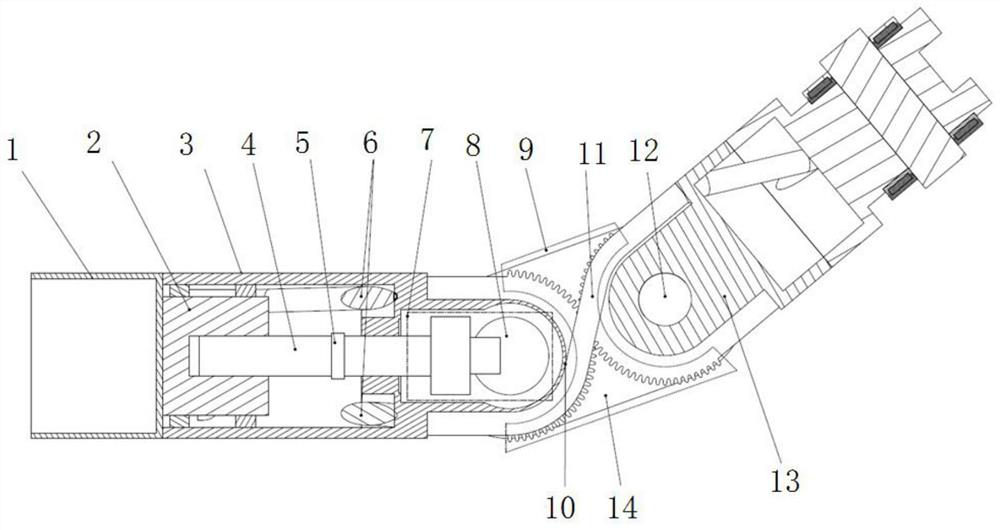
[0049] Such as figure 1 As shown, the mechanical arm joint includes the articulated arm driven part 13 connected to the shaft connecting plate 14 through the rotating shaft b12, and the active part of the articulated arm connected to the shaft connecting plate 14 through the rotating shaft a8;

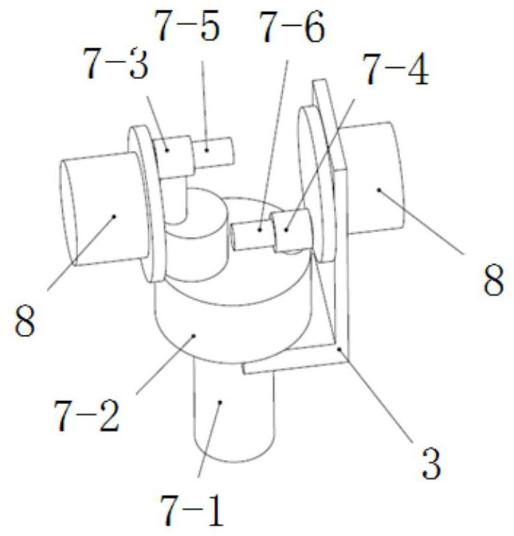
[0050] The active part includes a fully enclosed cavity 1 , a semi-closed cavity 3 , and a driver 2 installed in the semi-closed cavity 3 , a drive shaft 4 , a torque sensor 5 and a drive transmission system 7 . Wherein the driving transmission system 7 is connected with the shaft connecting plate 14 through the rotating shaft a8;

[0051] The drive shaft 4 is located on the axis of the active part. When the driver 2 drives the drive shaft 4 to rotate, the torque sensor 5 transmits the rotation data, and the drive shaft 4 rotates to drive the drive transmission system 7 connected to the end to rotate;

[0052] The pipelines and lines between the fully enclosed chamber 1 and the semi-e...

Embodiment 2

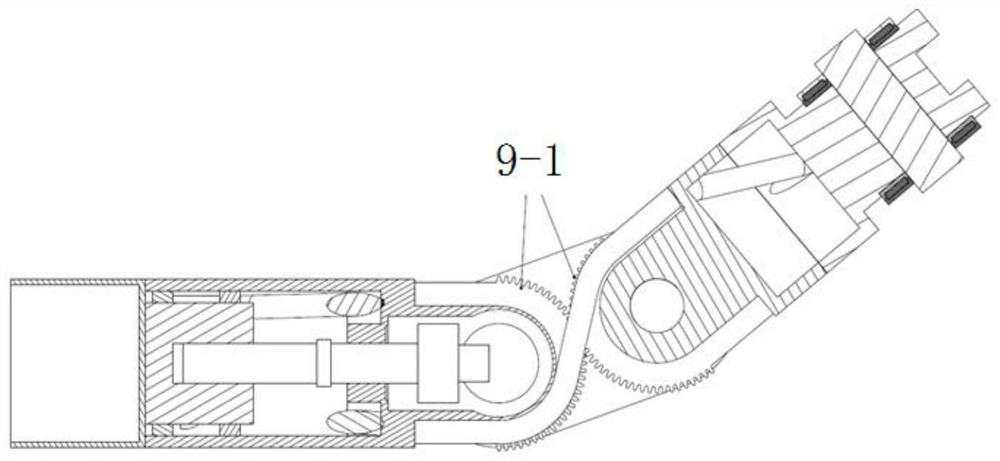
[0066] The driving transmission system 7 can also be a transmission mechanism composed of a pair of gears, the two gear shafts are perpendicular to each other, and the gears are a pair of meshing bevel gears or spiral bevel gears or straight bevel gears.

[0067] This structure is relatively simple, and the transmitted angle can be adjusted according to the transmission ratio of the gear pair, but the transmitted torque is not large. The main gear is installed on the driving shaft 7-1, and the auxiliary gear is installed on the rotating shaft a8. The rest are the same as in Example 1

Embodiment 3

[0069] In this embodiment, the relevant structure of the drive transmission system 7 in the articulated arm is as follows:

[0070] Such as Figure 5 As shown, the main transmission shaft 7-21 is installed in the active mechanical arm 7-36 (which is equivalent to the cavity of the active part), and two internal main gears 7-22 and end internal gears 7-31 are installed on the main transmission shaft 7-21. , the vertical internal gear 7-23 and the inner end vertical gear 7-33 are installed on the inner wall of the active mechanical arm 7-36, and the external main gear 7-24 (equivalent to that of embodiment 1) is installed on the outer wall of the active mechanical arm 7-36. Two external meshing gears 9-1) and a connecting plate 7-27 (equivalent to the shaft connecting plate 14 in the embodiment), wherein the connecting plate 7-27 is installed through the rotating shaft a7-26 (equivalent to the rotating shaft a8), A sensor 7-34, which is an angle sensor or an angular velocity se...


PUM


Abstract

The invention belongs to the fusion reactor operation and maintenance technology, and particularly relates to a long-arm-span mechanical arm joint in a large-magnetic-field high-vacuum strong-radiation environment. The long-arm-span mechanical arm joint comprises a joint arm driven part connected with a shaft connecting plate through a rotating shaft b, and a joint arm driving part connected with the shaft connecting plate through a rotating shaft a; the driving part comprises a totally-closed cavity, a semi-closed cavity, a driver, a driving shaft, a torsion sensor and a driving transmission system, wherein the driver, the driving shaft, the torsion sensor and the driving transmission system are installed in the semi-closed cavity; the driving transmission system is connected with the shaft connecting plate through a rotating shaft a8; and the driver is moved out of the position of the rotating shaft through an effective transmission mechanism, the driver can obtain a larger space, the output torque is increased, the driver obtains more space, the space can be used for increasing power and can also be used for increasing shielding, and a mechanical arm is more resistant to radiation.

Description

technical field [0001] The invention belongs to the operation and maintenance technology of fusion reactors, and in particular relates to a mechanical arm joint with a long arm extending into a cavity for maintenance. Background technique [0002] The fusion experimental device and the fusion reactor teleoperation robot operate in a very harsh environment. After the reactor is shut down, extremely strong gamma radiation will be produced, and there will be radioactive dust and gas in the reactor. In the environment of strong magnetic field and high vacuum, the robotic arm entering the chamber for maintenance must face the challenges of harsh environments such as strong magnetic field, high vacuum, strong radiation, and pollutant contamination in a limited space. Existing robotic arms are all long-armed robotic arms. Due to limited space, their joints are divided into three categories: [0003] The first type is a closed joint in which the driver is directly on the joint shaf...

Claims


Application Information

Patent Timeline
Patent Type & Authority Applications(China)
IPC IPC(8): B25J17/02
CPCB25J17/02Y02E30/10
Inventor 黄超李鹏远王才旺罗蓉蓉陈辉邓华林闫腾飞
Owner SOUTHWESTERN INST OF PHYSICS
Why Eureka
Try Eureka