

Well drilling method and device
A drilling and drilling fluid technology, applied in the field of drilling methods and devices, can solve the problems of reducing the effective production time of oil wells, high cost of drilling equipment relocation, affecting the normal production of oil wells, etc. The effect of the punch cycle
- Summary
- Abstract
- Description
- Claims
- Application Information
AI Technical Summary
Problems solved by technology
Method used
Image

Examples
Embodiment 1
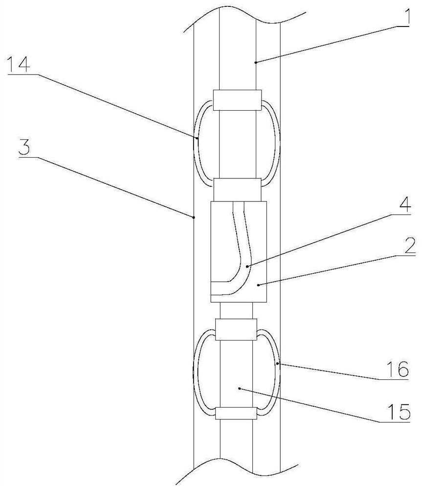
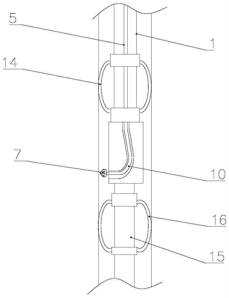
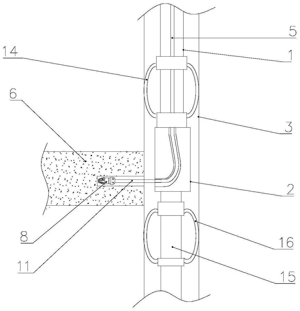
[0072] Such as Figure 1-3 As shown, the embodiment of the present application discloses a drilling device, which includes: a steering assembly and a drilling assembly. Wherein, the guide assembly includes tubing 1 and a guider, and the guider is arranged at the bottom end of the tubing 1, and both the tubing 1 and the guider are arranged in the casing 3; The perforating unit and the drilling unit for drilling the formation 6, the perforating unit includes a perforating drill bit 7, the diameter of the perforating drill bit 7 is 30-80mm, the drilling unit comprises a drilling drill bit 8, and the drilling unit of the perforating drill bit 8 The diameter is not greater than the diameter of the perforating drill bit 7; the perforating drill bit 7 can enter the oil pipe 1 through the coiled tubing 5, and punch the casing 3 through the guide to form the first through hole; the drilling bit 8 can pass through the connecting pipe Enter the oil pipe 1, and drill the formation 6 thro...
Embodiment 2
[0104] Such as Figure 7-8 As shown, the difference between this embodiment and Embodiment 1 is that the guide is a tilting device 17, which is a cylindrical structure, and the top wall of the tilting device 17 is an inclined surface, and the inclined surface is inclined downward. The angle is 1°-5°, preferably 3°; the diameter of the hole drill 7 is 50-80mm, preferably 72mm. By setting the guide as a skewer 17, the hole drill 7 directly passes through the inside of the casing 3, and changes direction under the action of the skewer, so that the hole drill 7 with a larger diameter can pass through the second passage smoothly. hole, so that the opening diameter of the casing 3 is larger, and then the diameter of the horizontal wellbore 9 is larger, so that the small-diameter casing 3 is provided with a large-diameter first through hole.
[0105] It can be understood that when the guider is a skewer 17, after the perforated drill bit 7 drills the casing 3, it needs to continue t...
Embodiment 3
[0111] Embodiment 3 of the present application provides a kind of drilling method, and this method can utilize the drilling device that embodiment 1 or embodiment 2 provides to realize, comprise the following steps:
[0112] (1) Connect the oil pipe and the guide, and lower it to the designated position of the casing;
[0113] Wherein, the lowering speed is 8-15m / min, preferably 10m / min.
[0114] (2) Lower the drilling unit into the oil pipe through the coiled tubing, and make the drilling bit of the drilling unit pass through the guide to drill holes in the casing to form the first through hole; after the drilling is completed, pull out the coiled tubing and drill Hole unit;
[0115] Wherein, the diameter of the hole drilling bit is 30-80 mm, and the rotation speed of the hole drilling bit is 100-300 r / min.
[0116] (3) The drilling unit is lowered into the tubing through the coiled tubing, and the drilling bit of the drilling unit is drilled through the guide and the first...
PUM
| Property | Measurement | Unit |
|---|---|---|
| Diameter | aaaaa | aaaaa |
| Diameter | aaaaa | aaaaa |
| Particle size | aaaaa | aaaaa |
Abstract
Description
Claims
Application Information