
Powder distributor for placing target material green bodies and sintering method of planar target material

A sintering method and target raw technology, which are applied in metal material coating process, ion implantation plating, lighting and heating equipment, etc., can solve the problems of target deformation, target bottom damage, difficult to breathe, etc., and reduce friction. Resistance, prevent deformation and cracking, improve the effect of breathability

Pending Publication Date: 2021-09-03
广州市尤特新材料有限公司
View PDF0 Cites 0 Cited by
  • Summary
  • Abstract
  • Description
  • Claims
  • Application Information

AI Technical Summary

Problems solved by technology

The first placement method is in close contact with the target green body and the setter plate, which is difficult to breathe, which may easily lead to insufficient sintering of the green body. Although the second placement method improves the air permeability, the target material is in contact with the gasket after sintering. A large area of ​​gasket marks will be left at the position of the target, which will damage the bottom layer of the target, and the damaged part of the target needs to be processed later, which increases material loss and man-hour cost
The green target body will shrink during sintering. Due to the two placement methods for sintering, the position where the green target body contacts the setter plate and / or the gasket will also generate a large frictional resistance, which will Prevent the shrinkage of the target green body, so that the deformation of the target shrinking at the contact position is different from the deformation at the non-contact position, resulting in deformation and cracking of the target
Therefore, there is another sintering method, which is to spread a layer of alumina powder on the setter first, and then place the target green body on the alumina powder for sintering, so as to reduce the friction caused by the shrinkage of the target. resistance, but in this way the gas flow cannot be achieved between the target and the setter

Method used


Image

  • Powder distributor for placing target material green bodies and sintering method of planar target material
  • Powder distributor for placing target material green bodies and sintering method of planar target material

Examples


Embodiment Construction

[0012] The invention will be described in further detail below in conjunction with specific embodiments.

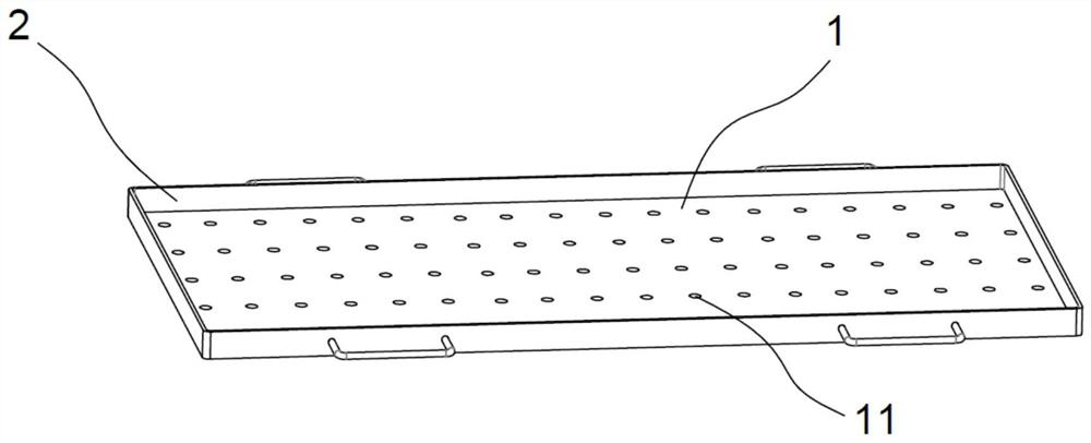
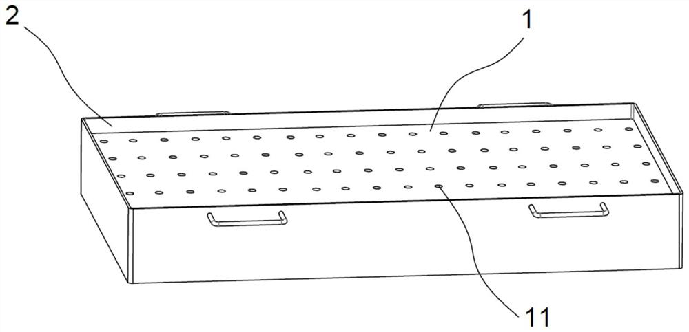
[0013] The powder distributor structure that the present invention adopts is as figure 1 , comprising a powder distributing plate 1, the top surface of the powder distributing plate 1 is the powder distributing surface, the powder distributing surface is provided with a plurality of circular powder leakage openings 11 with equal diameters, and the distance between adjacent powder leakage openings 11 is 25-45 mm, The diameter of powder leaking port 11 is 3~6mm. When in use, place the powder distributing plate 1 horizontally on the setter plate so that each powder leakage port 11 is on the same plane. Since the angle of the powder distribution plate 1 is horizontal, no matter whether the setter plate is bent or deformed, the powder distribution plate The periphery of 1 can be supported on the setter plate, so that there will be a space at the bottom for distributing alumin...


PUM

PropertyMeasurementUnit
diameteraaaaaaaaaa

Abstract

The invention relates to a powder distributor for placing target material green bodies and a sintering method of a planar target material. A plurality of powder stacks are stacked on a setter plate by using auxiliary sliding powder, then the target material green bodies are flatly placed on the powder stacks for sintering, the powder stacks are spaced by a certain distance, and the vertexes of the powder stacks are higher than the top surface of the setter plate. The contact area of the target material green bodies, the auxiliary sliding powder and the setter plate is reduced, so that the target material green bodies are prevented from making close contact with the auxiliary sliding powder and the setter plate, the air permeability between a target material and the setter plate is improved, the target material is fully sintered, and auxiliary volatile matter in the sintering process can be smoothly discharged through the air-permeable intervals between the adjacent powder stacks. The sliding effect of the auxiliary sliding powder formed into the powder stacks is better than that of a flat laid layer in the prior art, the friction resistance between the target material and the setter plate can be better reduced, the target material green bodies can be shrunk with small resistance in the sintering process, and deformation and cracking caused by friction force are effectively prevented.

Description

technical field [0001] The invention relates to the technical field of ceramic target sintering, in particular to a powder distributor for placing target green bodies and a sintering method for planar targets. Background technique [0002] In the traditional process of sintering planar ceramic targets, the target green body is mainly placed in the following ways. The first way is to place the green body directly on the setter for sintering; the second way is to put it The method is to place a gasket on the setter first, and then place the green target body on the gasket for sintering. The gasket supports the green target body to leave a ventilation channel between the green target body and the setter plate. The first placement method is in close contact with the target green body and the setter plate, which is difficult to breathe, which may easily lead to insufficient sintering of the green body. Although the second placement method improves the air permeability, the target...

Claims


Application Information

Patent Timeline
Patent Type & Authority Applications(China)
IPC IPC(8): F27B21/00F27D5/00C23C14/34
CPCF27B21/00F27D5/0006C23C14/3414
Inventor 周昭宇周志宏肖世洪雷雨汪政军
Owner 广州市尤特新材料有限公司
Learn More