Porous flow field fuel cell monomer without bipolar plate and series-parallel electric pile structure

A fuel cell and bipolar plate technology, applied in fuel cells, fuel cell parts, circuits, etc., can solve problems such as poor cooling consistency, reduced battery performance, increased flow resistance, and droplet discharge, achieving increased Effects of electrode effective reaction area, reduction and number of end plates, reduction in weight and volume

Active Publication Date: 2021-09-03
GUANGZHOU INST OF ENERGY CONVERSION - CHINESE ACAD OF SCI
View PDF16 Cites 3 Cited by
  • Summary
  • Abstract
  • Description
  • Claims
  • Application Information

AI Technical Summary

Problems solved by technology

[0007] The existing fuel cell flow field design mainly has the following problems: 1. Due to the presence of ridges in the flow field of grooves and ridges, the mass transfer resistance of the reactant gas entering the area under the ridge in the membrane electrode is increased, resulting in the concentration of the reactant gas in the membrane electrode. The distribution is uneven, thereby reducing the performance of the battery; 2. The gas in the porous flow field may be short-circuited, the reactants are not evenly distributed, and the increase in flow resistance is not conducive to the discharge of the droplets produced by the reaction, which is likely to cause the cathode to "flood" ", also reduce the performance of the battery, and even cause damage to the electrodes; 3. The cooling consistency is not good, resulting in a large temperature difference inside the battery, and the local "hot spot" phenomenon will seriously affect the battery life
In addition, in terms of stack structure design, the series-parallel connection of fuel cell modules needs to be connected by end plate structure, which is large in size and complex in structure

Method used


Image

  • Porous flow field fuel cell monomer without bipolar plate and series-parallel electric pile structure
  • Porous flow field fuel cell monomer without bipolar plate and series-parallel electric pile structure
  • Porous flow field fuel cell monomer without bipolar plate and series-parallel electric pile structure

Examples


Embodiment

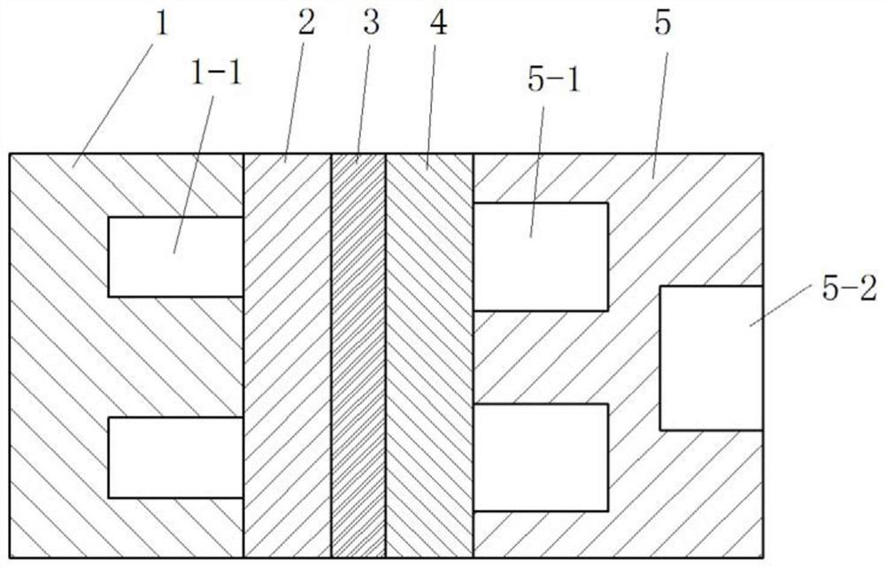
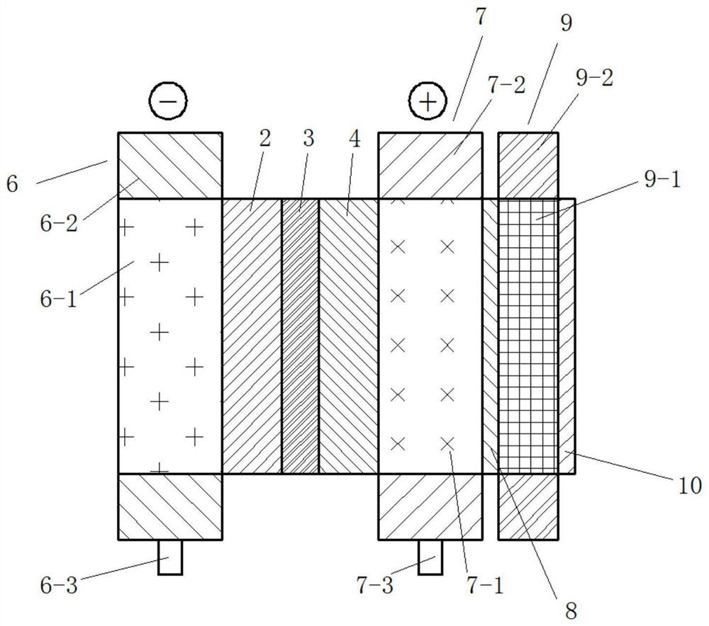
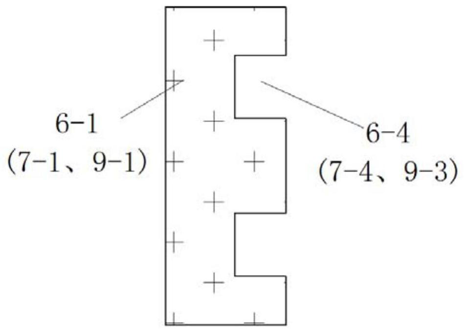
[0041] see Figure 1 to Figure 7 , figure 1 It is a schematic diagram of a traditional graphite plate fuel cell; figure 2 It is a schematic diagram of a single porous flow field fuel cell without a bipolar plate in the present invention; image 3 It is a schematic cross-sectional view of the porous material of the present invention along the flow channel in the thickness direction; Figure 4 It is a schematic diagram of the non-uniform porosity layout of the porous material of the present invention; Figure 5 It is a schematic diagram of parallel connection of shared anodes of two fuel cell monomers in the present invention; Figure 6 It is a schematic diagram of the parallel connection of two fuel cell monomers sharing the cooling layer in the present invention; Figure 7 It is a schematic diagram of the structure of the series-parallel stack of the present invention.

[0042] Such as figure 1 As shown, the traditional graphite plate fuel cell consists of an anode flow...


PUM

PropertyMeasurementUnit
porosityaaaaaaaaaa

Abstract

The invention discloses a porous flow field fuel cell monomer without a bipolar plate. Themonomer comprises an anode porous layer, an anode gas diffusion layer, a membrane electrode, a cathode gas diffusion layer, a cathode porous layer, a cathode baffle plate, a cooling porous layer and an anode baffle plate, the anode porous layer or the cathode porous layer or the cooling porous layer is formed by embedding a porous material into a solid frame, and the cathode baffle separates the cathode porous layer from the cooling porous layer. The invention also provides a series-parallel electric pile structure of a fuel cell. Through reasonable design of the structure, porosity and permeability, the flow resistance of a porous flow field is effectively reduced, and the fluid distribution uniformity is improved, so that the effective utilization rate of an electrode reaction area is increased, and the performance of the fuel cell is improved. By using the design of sharing the anode porous layer or sharing the cooling porous layer, fuel cell monomers are connected in parallel to form the Ns x Np section series-parallel electric pile structure, so that the size of an electric pile is reduced, and the power density of the electric pile is improved.

Description

technical field [0001] The invention relates to the technical field of fuel cells, in particular to a porous flow field fuel cell unit without a bipolar plate and a series-parallel electric stack structure. Background technique [0002] Fuel cells directly convert fuel chemical energy into electrical energy. They have the advantages of high energy conversion efficiency, low noise, and zero emissions. They are ideal mobile power sources and have broad application prospects in the fields of automobiles, drones, ships, and electronic products. . The function of the flow field of the fuel cell is to distribute the reactants to the entire active area of ​​the fuel cell. Therefore, the design of the flow field and the bipolar plate should satisfy the uniform distribution of the reactants, as well as good cooling and heat dissipation performance, electrical conductivity, drainage, and structure. stability etc. In order to meet these requirements at the same time, in addition to t...

Claims


Application Information

Patent Timeline
Patent Type & Authority Applications(China)
IPC IPC(8): H01M8/026H01M8/0265H01M8/0273H01M8/0297
CPCH01M8/026H01M8/0265H01M8/0297H01M8/0273Y02E60/50
Inventor 蒋方明魏琳廖梓豪郭剑
Owner GUANGZHOU INST OF ENERGY CONVERSION - CHINESE ACAD OF SCI
Why Eureka
Try Eureka