Air purification spraying device for printing and dyeing room and spraying control method of air purification spraying device

A technology of air purification and spraying device, which is applied in the field of air purification, can solve the problems of waste of resources and reduce work efficiency, and achieve the effects of avoiding dripping, reducing impact force and increasing the spraying range

Active Publication Date: 2021-09-07
桐乡市京都印染股份有限公司
View PDF17 Cites 0 Cited by
  • Summary
  • Abstract
  • Description
  • Claims
  • Application Information

AI Technical Summary

Problems solved by technology

[0004] The purpose of the present invention is to provide an air purification spraying device for a printing and dyeing room and a spraying control method thereof, so as to solve the problem that the existing printing and dyeing room proposed in the above background technology cannot be changed according to the actual air conditions in different areas inside the printing and dyeing room during air purification. Wide range spraying or fixed-point spraying in some areas with relatively serious air quality, resulting in indiscriminate spraying. In areas with severe air quality, secondary or multiple spraying is required, which not only wastes resources but also reduces work efficiency. question

Method used


Image

  • Air purification spraying device for printing and dyeing room and spraying control method of air purification spraying device
  • Air purification spraying device for printing and dyeing room and spraying control method of air purification spraying device
  • Air purification spraying device for printing and dyeing room and spraying control method of air purification spraying device

Examples


Embodiment

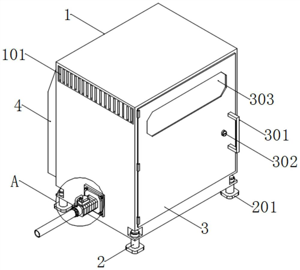
[0040] Example: such as Figure 1-7 As shown, the air purification spraying device and spraying control method for the printing and dyeing room, including the main body box 1;

[0041] The suction pump 5 is arranged on the left and right sides of the main body box 1, and is used to pump the water source into the main body box 1 for circulation and discharge;

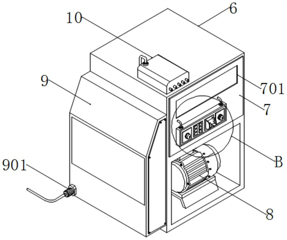
[0042] The main frame 6 is arranged inside the main box 1, and is used to place the control box 7, the motor 8, and the distribution box 9. The top of the main box 1 is equipped with a remote control box 10, which is used to receive signals from the remote controller and realize remote control. ;

[0043] The motor box 4 is arranged on the back side of the main box 1, and is used to connect the external power supply to energize the equipment, so as to start the equipment with electricity for working.

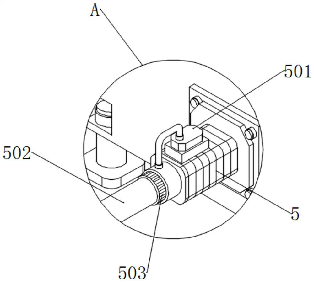
[0044] The shower 11 is arranged at one end of the water pipe 502 , and is used for injecting water into the shower 11...


PUM


Abstract

The invention discloses an air purification spraying device for a printing and dyeing room, and belongs to the technical field of air purification. The device comprises a main body box and suction pumps arranged in the left side and the right side of the main body box and used for pumping a water source into the main body box for circulation and then discharging. The device overcomes the defects in the prior art, multiple sprayers can be installed at the upper end of a water pipe by screwing connectors into the water pipe one by one through sprayers, an adjusting ring, nozzles and the connectors, the spraying direction of the device is effectively increased, and after the adjusting ring moves up and down, the impact force generated when water flow collides with the adjusting ring can be adjusted; water flow can be extruded out of the nozzles at different injection speeds according to the magnitude of impact force to be sprayed, then the spraying range of the device is changed, and the device can conduct wide-range spraying or fixed-point spraying on part of areas with serious air quality according to the actual air conditions of different areas in the printing and dyeing room, resources are saved, and the working efficiency is improved.

Description

technical field [0001] The invention relates to the technical field of air purification, in particular to an air purification spray device for a printing and dyeing room and a spray control method thereof. Background technique [0002] Air purification refers to providing overall solutions for various indoor environmental problems such as sterilization and disinfection, dust reduction and haze removal, removal of harmful decoration residues and peculiar smells, improving living and office conditions, and improving physical and mental health. Indoor environmental pollutants and pollution sources mainly include Radioactive gas, mold, particulate matter, decoration residue, second-hand smoke, etc. [0003] When the air is purified in the existing printing and dyeing room, it is not possible to change the wide-area spraying according to the actual air conditions in different areas inside the printing and dyeing room or to perform fixed-point spraying in some areas with relativel...

Claims


Application Information

Patent Timeline
IPC IPC(8): B01D47/06B01D53/18C02F9/04C02F103/18
CPCB01D47/06B01D53/18C02F9/00C02F1/66C02F1/50C02F1/28C02F1/001C02F1/52C02F1/5281C02F2103/18C02F2303/02
Inventor 不公告发明人
Owner 桐乡市京都印染股份有限公司
Why Eureka
Try Eureka