
A workbench for intelligent motor assembly based on pneumatic and hydraulic structure principles

A technology for assembling workbenches and structural principles, applied in electromechanical devices, manufacturing motor generators, and cleaning methods using tools, etc., can solve problems such as affecting user experience of cleaning efficiency, reducing work efficiency, and being easily affected by dust.

Active Publication Date: 2021-11-02
徐州亚泰电机有限公司
View PDF5 Cites 0 Cited by
  • Summary
  • Abstract
  • Description
  • Claims
  • Application Information

AI Technical Summary

Problems solved by technology

During the assembly process of the motor, when the rotor just enters the stator, due to the magnetic force, the rotor will be attracted and shifted, causing the outer ring of the rotor to fit the inner ring of the stator, so that the central axes of the rotor and the stator are not in a straight line. Locate the threaded holes used for alignment and installation. Due to the attractive force between the stator and the rotor, it is difficult to ensure that the stator and the rotor are concentric during assembly. The stator core is easy to scratch the latitude-free belt, which will cause scratches when the motor is running. At the same time, there are hidden dangers of magnetic steel falling off and motor failure, which makes assembly difficult, increases the time required for assembly, and reduces work efficiency.
[0004] The motor is generally assembled on the assembly workbench, and the general motor has a built-in magnetic structure. During assembly, it is easy to attract small particles of dust or debris, which affects the assembly effect of the motor. On the other hand, the assembly work Due to the long-term use of the platform, its surface is easy to attract and accumulate a large amount of dust due to static electricity. When assembling the motor, it is easily affected by the dust, which affects the accuracy and service life of the assembled motor. At the same time, when cleaning the dust, due to The dust in the dust cup is not concentrated, and it is easy to adhere to the inside of the dust cup and other parts, so there is a problem of dust pollution when emptying the dust, which greatly affects the user experience and cleaning efficiency

Method used


Image

  • A workbench for intelligent motor assembly based on pneumatic and hydraulic structure principles
  • A workbench for intelligent motor assembly based on pneumatic and hydraulic structure principles
  • A workbench for intelligent motor assembly based on pneumatic and hydraulic structure principles

Examples


Embodiment Construction

[0027] The technical solution of this patent will be further described in detail in conjunction with specific implementation below, and the technical features or connection relationships described in the present invention are not described in detail. The prior art is used. The present invention will be described in further detail below in conjunction with the accompanying drawings.

[0028] In describing the present invention, it should be understood that the terms "upper", "lower", "front", "rear", "left", "right", "top", "bottom", "inner", " The orientation or positional relationship indicated by "outside", etc. is based on the orientation or positional relationship shown in the drawings, and is only for the convenience of describing the present invention and simplifying the description, rather than indicating or implying that the referred device or element must have a specific orientation, so as to Specific orientation configurations and operations, therefore, are not to be...


PUM


Abstract

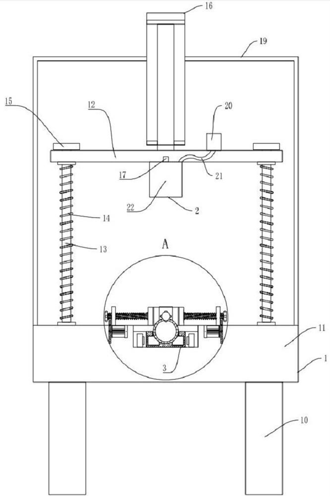
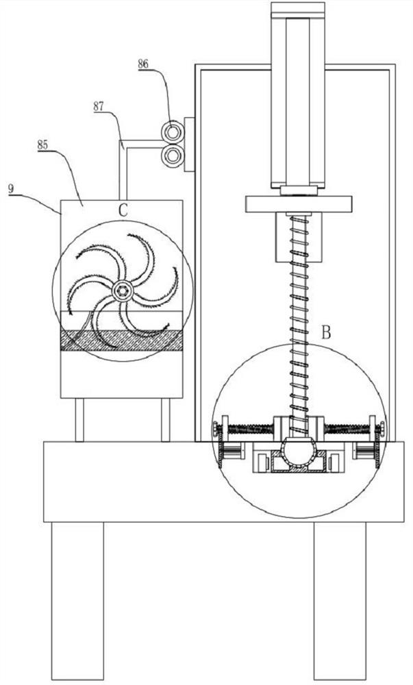
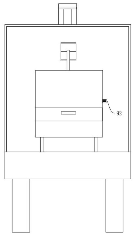
The invention discloses a workbench for intelligent motor assembly based on pneumatic and hydraulic structure principles, including a main body, an inflatable extrusion type self-adaptive precise positioning rotor clamping device, and a condensation type clamping type self-adaptive precise positioning rotor clamping device , Precise positioning synchronous primary drive device, precise positioning synchronous secondary drive device, precise positioning synchronous three-stage drive device, precise positioning synchronous four-stage drive device, retractable self-adaptive precise positioning stator clamping mechanism and dust Self-filtering recovery and cleaning adsorption device in the box. The invention belongs to the technical field of workbench for intelligent assembly of motors, and specifically refers to a workbench for intelligent assembly of motors based on the principle of air pressure and hydraulic structure; , such as the use of air cushions, hydrostatic pressure, and fluid dynamic pressure to generate cushioning functions) applied to the field of motor intelligent assembly technology.

Description

technical field [0001] The invention belongs to the technical field of a workbench for intelligent motor assembly, and specifically refers to a workbench for intelligent motor assembly based on pneumatic and hydraulic structural principles. Background technique [0002] A motor is an electromagnetic device that converts or transmits electrical energy according to the law of electromagnetic induction. The main function of the motor is to generate driving torque as a power source for electrical appliances or various machines. [0003] During the assembly process of the motor, the rotor needs to be put into the combination of the stator and the casing assembled in advance. In the prior art, the stator is usually fixedly installed in the motor casing, and the rotor is emptied inside the stator through the end cover bearing. , leaving an air gap between the stator and rotor. During the assembly process of the motor, when the rotor just enters the stator, due to the magnetic for...

Claims


Application Information

Patent Timeline
Patent Type & Authority Patents(China)
IPC IPC(8): B23P19/027B08B5/04B08B1/00B08B1/04B01D47/02H02K15/00
CPCB23P19/006B23P19/027B08B5/04B08B1/001B08B1/04B01D47/02H02K15/00
Inventor 苗培华
Owner 徐州亚泰电机有限公司
Learn More