Mechanical automatic unloading device

A kind of unloading device and mechanical technology, applied in the direction of conveyor, conveyor objects, loading/unloading, etc., can solve the problems of low unloading load capacity and low efficiency of single unloading, so as to improve unloading efficiency and reduce the number of shutdowns Effect

Active Publication Date: 2021-09-07
李小玲 +2
View PDF10 Cites 6 Cited by
  • Summary
  • Abstract
  • Description
  • Claims
  • Application Information

AI Technical Summary

Problems solved by technology

[0004] 1. The comparative document CN110171788A discloses an unloading rack for logistics transportation, "including a device bracket, a push mechanism, a transport bracket, a limit bracket, a transport mechanism, a lifting mechanism, a power mechanism, an unloading bracket and an unloading mechanism, which can be pushed through the push plate. Ⅱ is in contact with the upper surface of the goods to be unloaded. Under the push of the lifting mechanism, the push plate Ⅱ squeezes the compression spring Ⅰ to push the unloading mechanism to slide on the unloading bracket, so that the unloading mechanism and the power mechanism are frictionally driven, and the power mechanism drives The friction wheel Ⅱ set on the unloading mechanism rotates, and the friction wheel Ⅱ drives the unloading threaded plate to rotate, and the unloading threaded plate drives the four clamping rods to slide closer to each other through the vortex thread, and the lower ends of the four bottom rods first touch the outer wall of the cargo. Contact, the four bottom rods slide down along the outer wall of the cargo under the push of the lifting mechanism, and are stuck on the bottom of the cargo under the action of the torsion spring to lift the cargo. When the device is unloading, the single unloading of the material The carrying capacity is low, resulting in low efficiency of single unloading of the device;

Method used


Image

  • Mechanical automatic unloading device
  • Mechanical automatic unloading device
  • Mechanical automatic unloading device

Examples


Embodiment Construction

[0038] The following will clearly and completely describe the technical solutions in the embodiments of the present invention with reference to the accompanying drawings in the embodiments of the present invention. Obviously, the described embodiments are only some, not all, embodiments of the present invention. Based on the embodiments of the present invention, all other embodiments obtained by persons of ordinary skill in the art without making creative efforts belong to the protection scope of the present invention.

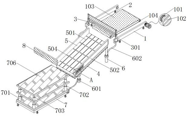
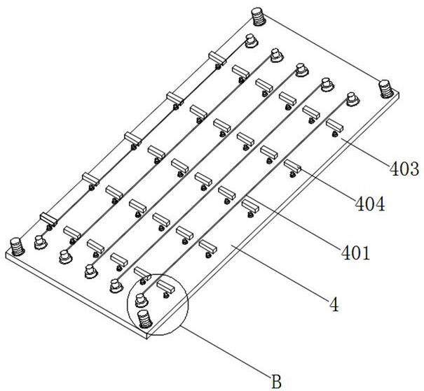
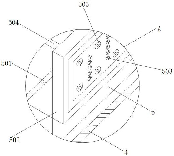
[0039] see Figure 1-Figure 8 , an embodiment provided by the present invention: a mechanical automatic unloading device, including a bottom plate 4 and a telescopic support column 6, the four corners of the bottom of the bottom plate 4 are equipped with telescopic support columns 6 through shafts, and the bottom plate 4 is used as a multifunctional unloading plate The auxiliary supporting device of 5 can assist it to realize the corresponding deceleration fun...


PUM


Abstract

The invention discloses a mechanical automatic unloading device. The mechanical automatic unloading device comprises a bottom plate and telescopic supporting columns. The telescopic supporting columns are mounted at the four corners of the bottom plate through shaft pieces. The top of the bottom plate is connected with a multifunctional unloading plate through a threaded column. The surfaces of the telescopic supporting columns are sleeved with lantern rings. The surfaces of the lantern rings are connected with traction ropes. The tail ends of the two traction ropes are connected with a vertical plate. A transfer intercepting structure is mounted at the top of the vertical plate. The tail ends of the other two traction ropes are connected with an auxiliary unloading plate. Moving pieces are mounted at the bottoms of the vertical plate and the auxiliary unloading plate. Protection plates are mounted on the two sides of the top of the multifunctional unloading plate. An embedding groove is formed in the front face of one protection plate. The front faces of the protection plates are in sliding connection with a blocking plate through the embedding groove. According to the mechanical automatic unloading device, through arrangement of the auxiliary unloading plate, the single-time unloading bearing capacity of the device can be improved, accordingly, the unloading frequency is reduced, and the unloading efficiency of the device is improved.

Description

technical field [0001] The invention relates to the technical field of unloading devices, in particular to a mechanical automatic unloading device. Background technique [0002] With the advancement of mechanical technology, more and more devices are gradually realizing automatic operation, which liberates the ancestors from heavy physical labor and facilitates the operation of the staff. From the perspective of corporate investors, it greatly reduces The thermal cost of the device provides better technical support for the company to create profits and improve efficiency. In the production process of the company, relevant materials need to be unloaded before they are put into production and after production. During this process, through The introduction of automation technology can greatly improve the unloading efficiency. [0003] The defective that existing unloading device exists is: [0004] 1. The comparative document CN110171788A discloses an unloading rack for logis...

Claims


Application Information

Patent Timeline
Patent Type & Authority Applications(China)
IPC IPC(8): B65G15/00B65G65/32B65G57/03B65G47/44
CPCB65G15/00B65G65/32B65G57/03B65G47/44
Inventor 李小玲吴云云孙运滨
Owner 李小玲
Why Eureka
Try Eureka