Fabricated concrete-filled steel tube double-layer gate-type pier structure

A concrete-filled steel tube and prefabricated technology, applied to bridge parts, bridges, buildings, etc., can solve problems such as short construction period, long construction period, and potential safety hazards, so as to reduce the cost of the whole life, reduce the construction time, and improve the use efficiency Effect

Active Publication Date: 2021-09-07
WUHAN UNIV OF TECH
View PDF8 Cites 0 Cited by
  • Summary
  • Abstract
  • Description
  • Claims
  • Application Information

AI Technical Summary

Problems solved by technology

At present, for the construction of bridges in highways, local roads and urban roads, the upper structure of the bridge has achieved prefabricated assembly construction, while most of the substructure of the bridge still uses the traditional technology for on-site pouring construction. In situations where the construction space is narrow, the construction period is short, and the construction quality is high, such as crossing rivers, lakes or roads, the conventional on-site pouring concrete construction scheme requires more formwork and scaffolding, the construction period is longer, and the quality and accuracy of on-site pouring are difficult. Guarantee, and the personal safety of construction workers on site is not guaranteed, there are certain hidden dangers

Method used


Image

  • Fabricated concrete-filled steel tube double-layer gate-type pier structure
  • Fabricated concrete-filled steel tube double-layer gate-type pier structure
  • Fabricated concrete-filled steel tube double-layer gate-type pier structure

Examples


Embodiment 1

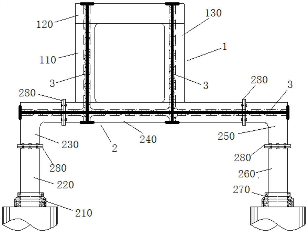
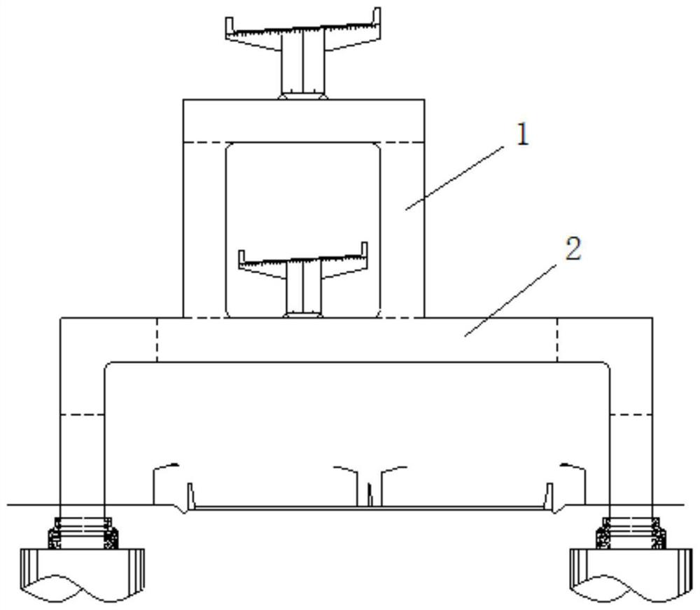
[0025] Such as Figure 1 ~ Figure 3 As shown, a prefabricated steel pipe concrete double-layer portal pier structure includes an upper portal pier 1 and a lower portal pier 2, and the upper portal pier 1 and the lower portal pier 2 are prestressed by welding and post-tensioning Rebar 3 composite connection.

Embodiment 2

[0027] Such as Figure 1 ~ Figure 3 As shown, the present embodiment is a further optimization carried out on the basis of embodiment 1, which is specifically as follows:

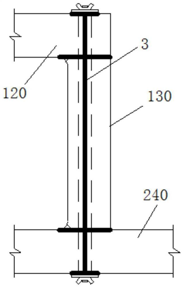
[0028] The upper gantry pier 1 includes a left upper column 110, an upper cover beam 1220 and a right upper column 130, and the left upper column 110 and the right upper column 130 are respectively arranged below the two ends of the upper cover beam 1220; the upper cover beam 1220, the left upper column 110 and the lower gantry Pier 2 is compositely connected by welding and post-tensioned prestressed steel bar 3; the upper cover beam 1220, right upper column 130 and lower door-type pier 2 are compositely connected by welding and post-tensioned prestressed steel bar 3, construction of post-tensioned prestressed steel bar The process belongs to the prior art, and will not be described in detail here.

Embodiment 3

[0030] Such as Figure 1 ~ Figure 3 As shown, the present embodiment is a further optimization carried out on the basis of embodiment 2, which is specifically as follows:

[0031] The upper left column 110, the upper cover beam 1220 and the upper right column 130 are all filled with concrete filled steel tubes.


PUM


Abstract

The invention relates to a fabricated concrete-filled steel tube double-layer gate-type pier structure which comprises an upper-layer gate-type pier and a lower-layer gate-type pier, and the upper-layer gate-type pier and the lower-layer gate-type pier are compositely connected through welding and post-tensioned prestressed reinforcements. The fabricated concrete-filled steel tube double-layer gate-type pier structure has the advantages that the double-layer gate-type pier is a structure which is composed of the double-layer stand columns and the cover beams, loads are transmitted to a foundation, under the background that urban land is increasingly strained, the double-layer gate-type pier provides a mode for building a double-layer bridge, the requirements for the line shape and the gradient in road design can be effectively met, the use efficiency of urban traffic is improved as much as possible in a limited urban space, the contradiction between urban land resources and traffic construction is relieved, and the method becomes the trend of urban bridge development.

Description

technical field [0001] The invention relates to the technical field of bridges, in particular to an assembled steel pipe concrete double-layer portal pier structure. Background technique [0002] With the high-speed construction of cities in our country, the built infrastructure has gradually been unable to carry the increasing traffic volume. Therefore, the construction and expansion of a large number of infrastructure in the city is the focus of urban development. When the proposed bridge obliquely spans existing roads or railways, oil or natural gas pipelines, and optical cables, the lower piers of the bridge are often designed as portal piers. [0003] The portal pier is a force-bearing structure composed of columns and cap beams that transmits the upper load to the foundation. According to the structural form, it is mainly divided into simply supported portal piers and rigidly connected portal piers. Simply supported portal piers have poor overall structural performanc...

Claims


Application Information

Patent Timeline
Patent Type & Authority Applications(China)
IPC IPC(8): E01D19/00E01D19/02
CPCE01D19/00E01D19/02
Inventor 康俊涛刘焱烁
Owner WUHAN UNIV OF TECH
Why Eureka
Try Eureka