
Generator set with compressed air as power

A technology of generating sets and compressed air, which is applied in the directions of engine components, engine lubrication, machine/engine, etc., and can solve problems such as destruction, great influence of natural environment, and difficulty in peak regulation

Pending Publication Date: 2021-09-07
许承革
View PDF0 Cites 0 Cited by
  • Summary
  • Abstract
  • Description
  • Claims
  • Application Information

AI Technical Summary

Problems solved by technology

[0003] At present, the power generation industry mainly includes thermal power generation systems, nuclear power generation systems, hydroelectric power generation systems, solar energy, and wind power generation systems, etc., but these power generation systems have some shortcomings. Thermal power generation systems burn coal, consume disposable mineral resources, and consume a lot of water resources. At the same time, the discharged pollutants carbon monoxide, sulfur dioxide, acidic substances, and dust seriously pollute the environment and air, and are the largest pollution source of climate change; nuclear power generation also consumes disposable mineral resources, and a large amount of minerals are consumed in the production of nuclear fuel. Pollution is particularly important The risk of nuclear power generation is particularly high. Once a nuclear leakage accident occurs, it will bring disasters to human beings. Nuclear waste disposal is a worldwide problem; hydroelectric power generation systems require huge investment and long recovery time, which destroys the ecological environment and changes the local climate. ; Solar power generation will cause damage to local vegetation, and power generation is greatly affected by the natural environment. It cannot generate power in rainy days or at night without the sun, and the power generation efficiency is low, and it is difficult to adjust peaks. Environment, the power generation is greatly affected by the natural environment, it is difficult to adjust the peak value, and the power generation efficiency is low

Method used


Image

  • Generator set with compressed air as power
  • Generator set with compressed air as power
  • Generator set with compressed air as power

Examples


Embodiment Construction

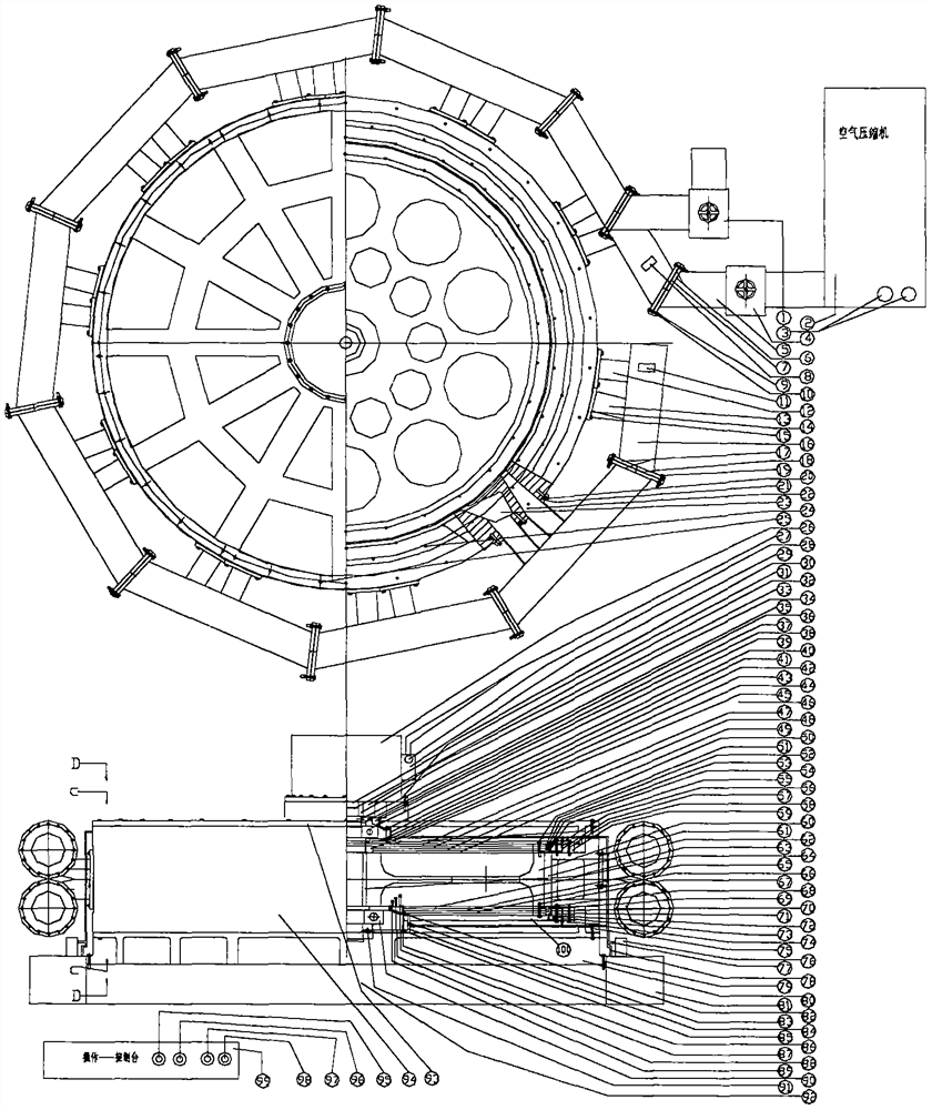
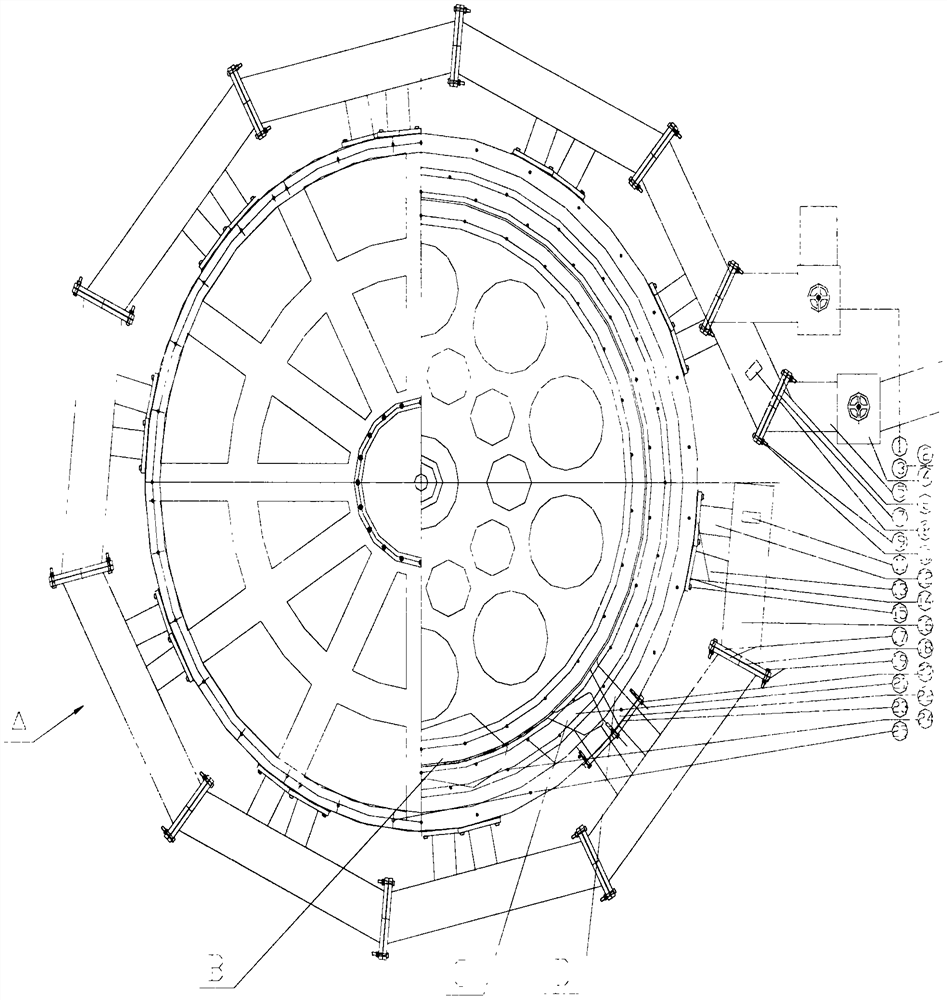
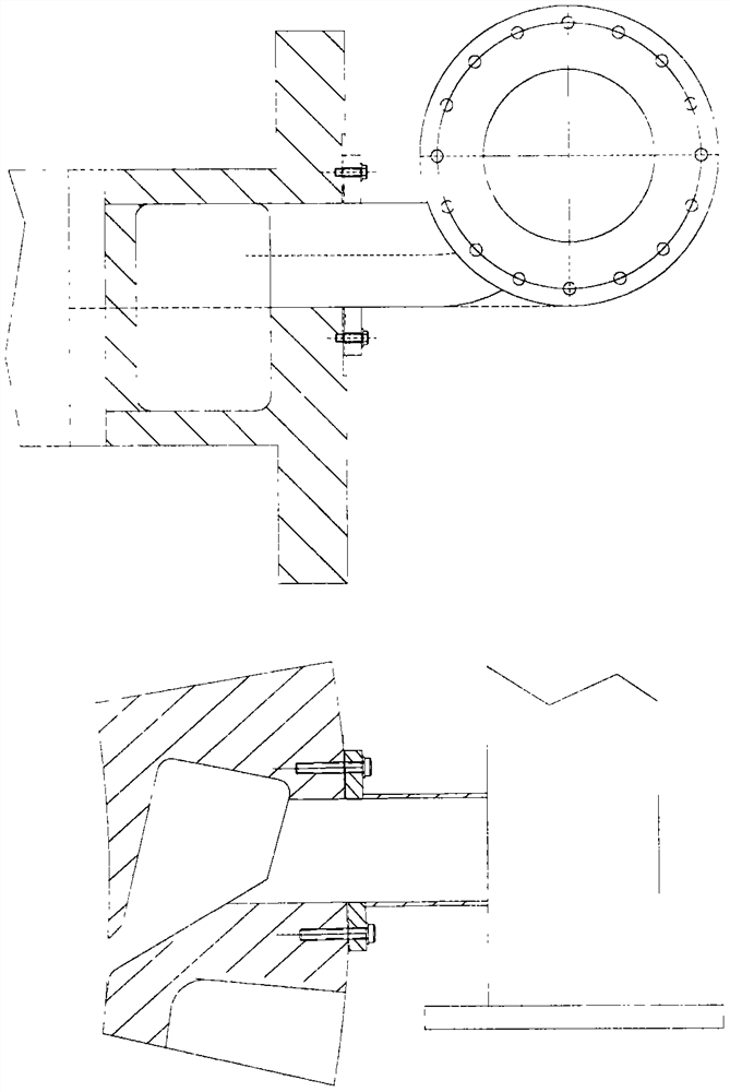
[0015] figure 1Middle: 1. Exhaust valve, 2. Diesel engine air compressor, 3. Safety switch, start switch, 4. Intake valve, 5. Intake pipe, 6. Intake pipe flange, 7. Intake pipe seal Pad, 8, air intake pipe barometer, 9, flange bolt, 10, flange nut, 11, air outlet pipe pressure gauge, 12, air outlet pipe elbow, 13, air inlet pipe elbow, 14, air outlet Air elbow flange, 15, inlet elbow flange bolts, 16, outlet pipe, 17, outlet pipe fixing flange, 18, outlet pipe sealing ring, 19, outlet pipe bolts and nuts, 20, outlet and inlet pipe method Blue bolts, 21, air intake storage box, 22, air outlet storage box, 23, air outlet air intake flange gasket, 24, stator sealing ring bolts, 25, generator base fixing bolts, 26, generator, 27, generator Power cord, 28. Generator fuse, 29. Power cord box, 30. Generator bolt nut, 31. Generator main shaft, 32. Rotor main shaft, 33. Coupling, 34. Flat key, 35. Sealing ring, 36. Fixed nut, 37. Bolt, 38. Bearing cover, 39. Bearing, 40. Oil return ...


PUM


Abstract

The invention provides a generator set with compressed air as power. The generator set with compressed air as power does not burn coal and does not use water, compressed gas in the natural environment is adopted as power, a diesel engine drives a compressor to work, diesel oil is combusted, and compared with a thermal power generation gas turbine oil injection mode, oil saving is obvious, and the exhausted tail gas reaches the national A6 emission standard after being treated. The generator set is made by the mechanical manufacturing technology, and is free of environmental interference, stable in operation, stable in power generation Hertz frequency, high in power generation efficiency, capable of running in a full-load mode all the year round, easy and convenient to maintain and long in service life.

Description

[0001] Technical field: [0002] The invention relates to a generating set powered by compressed air, which is a new generating set using a diesel engine to drive an air compressor to realize power generation. Background technique: [0003] At present, the power generation industry mainly includes thermal power generation systems, nuclear power generation systems, hydroelectric power generation systems, solar energy, and wind power generation systems, etc., but these power generation systems have some shortcomings. Thermal power generation systems burn coal, consume disposable mineral resources, and consume a lot of water resources. At the same time, the discharged pollutants carbon monoxide, sulfur dioxide, acidic substances, and dust seriously pollute the environment and air, and are the largest pollution source of climate change; nuclear power generation also consumes disposable mineral resources, and a large amount of minerals are consumed in the production of nuclear fuel....

Claims


Application Information

Patent Timeline
IPC IPC(8): F01D15/10F01D1/06F01D11/08F01D25/16F01D25/18F02B63/06F16J15/16F16L23/026F16L23/18F16N7/38
CPCF01D15/10F01D1/06F01D11/08F01D25/16F01D25/18F02B63/06F16L23/026F16L23/18F16N7/38F16J15/16
Inventor 许承革
Owner 许承革
Learn More