Manufacturing method of novel automatic cleaning solar street lamp
A technology for solar street lamps and automatic cleaning, applied in cleaning methods and appliances, cleaning methods using tools, chemical instruments and methods, etc., can solve the problem of inability to adjust the direction of solar panels facing the sun according to seasonal changes, affecting the utilization of solar panels, Problems such as poor cleaning effect of lamps and lanterns, to achieve the effect of ensuring normal operation, easy cleaning, and avoiding use
- Summary
- Abstract
- Description
- Claims
- Application Information
AI Technical Summary
Problems solved by technology
Method used
Image
Examples
Embodiment 1
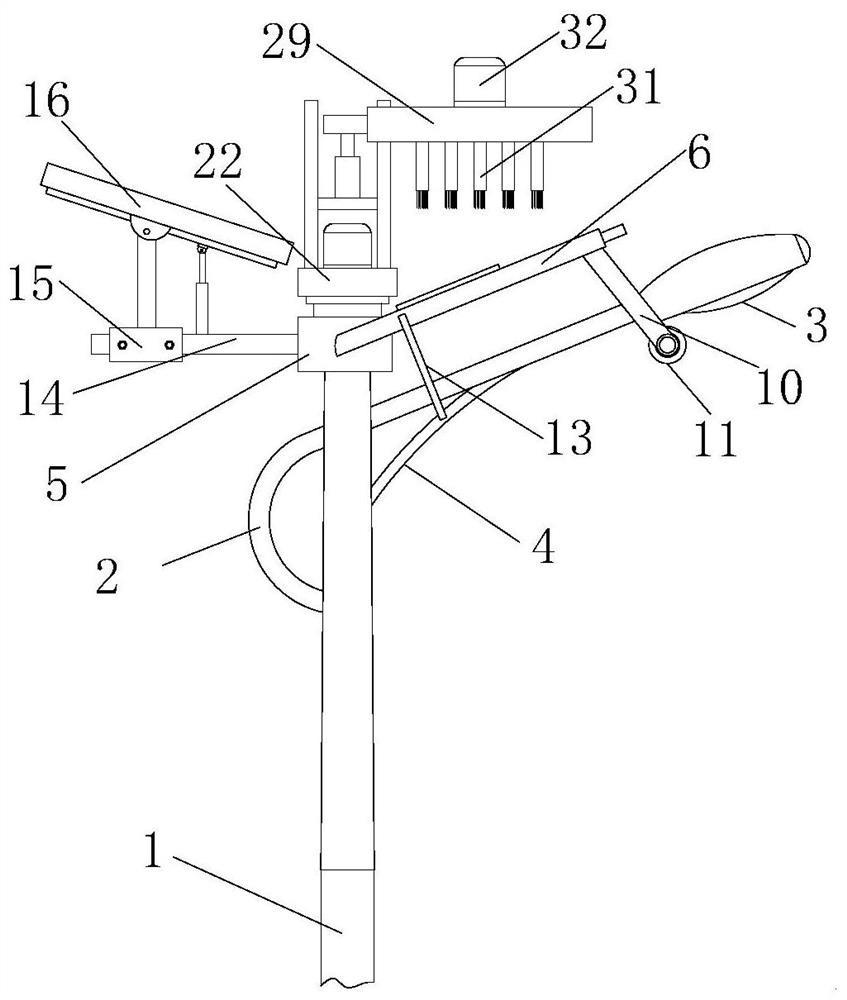
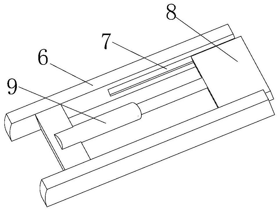
[0032] see figure 1 , figure 2 and Figure 4 , the cleaning assembly includes a fixed frame 6, a sliding plate 8, a first electric push rod 9, a mounting rod 10, a cleaning roller 11 and a first motor 12, the fixed frame 6 is fixedly connected to the two ends of the mounting block 5, and the fixed frame 6 The inner side is provided with a sliding groove 7, the sliding plate 8 is slidably connected in the sliding groove 7, the first electric push rod 9 is fixedly installed on the middle part of the fixed frame 6, and the output end of the first electric push rod 9 is fixedly connected to the bottom of the sliding plate 8. One end; one end of the sliding plate 8 is fixedly connected with two installation rods 10, and the cleaning roller 11 is connected with rotation between the two installation rods 10, and one end of one of the installation rods 10 is fixedly installed with the first motor 12, the first motor 12 The output end is fixedly connected to one end of the rotating ...
Embodiment 2
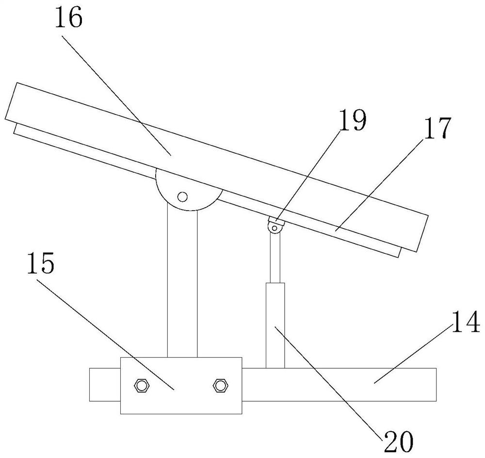
[0034] see figure 1 and image 3 , the adjustment assembly includes a fixed frame 17, a sliding piece 19 and a second electric push rod 20, the fixed frame 17 is fixedly connected to the bottom of the solar panel 16, the sliding piece 19 is matched and slidably connected to the inner side of the fixed frame 17, the second electric push rod The rod 20 is fixedly connected to the top of the connecting rod 14, and one end of the slider 19 is fixedly connected to the output shaft of the second electric push rod 20; During the process, it will slide in the fixed frame 17, so that the sliding member 19 will make the solar panel 16 rotate around the support frame 15 during the lifting process, so as to realize the adjustment of the sun-facing direction of the solar panel 16, so that it can be adjusted according to the season. Change and adjust the sun-facing direction of the solar battery panel 16, so that the utilization rate of solar energy reaches the best state.
Embodiment 3
[0036] see figure 1 , Figure 5 and Figure 6 , the rotating lifting assembly includes a rotating member 22, a bearing 23, a servo motor 24, a sliding column 25, a fixed plate 26, a third electric push rod 27 and a moving block 28, the bearing 23 is fixedly connected to the side wall of the mounting column 21, and the rotating member 22 Fixedly connected to the side wall of the bearing 23, and the bottom end of the rotating part 22 is supported on the top of the mounting column 21, the servo motor 24 is fixedly installed on the top of the rotating part 22, and the output end of the servo motor 24 is fixedly connected to the top of the mounting column 21 The fixed plate 26 is fixedly connected to the side wall of the sliding column 25, the third electric push rod 27 is fixedly installed on the top of the fixed plate 26, and the moving block 28 is fixedly connected to the output end of the third electric push rod 27; The middle part of the side is provided with a sliding circu...
PUM
 Abstract
Description
Claims
Application Information
 - R&D
- Intellectual Property
- Life Sciences
- Materials
- Tech Scout
- Unparalleled Data Quality
- Higher Quality Content
- 60% Fewer Hallucinations
Browse by: Latest US Patents, China's latest patents, Technical Efficacy Thesaurus, Application Domain, Technology Topic, Popular Technical Reports.
© 2025 PatSnap. All rights reserved.Legal|Privacy policy|Modern Slavery Act Transparency Statement|Sitemap|About US| Contact US: help@patsnap.com


