Cable core identification device and method

A cable and core technology, applied in the field of cable core identification device, can solve problems such as difficult to guarantee correct rate, inconvenient to carry, complex environment, etc., to achieve the effect of preventing miswiring, reliable design principle, and simple operation

Pending Publication Date: 2021-09-07
国网山东省电力公司肥城市供电公司 +2
View PDF6 Cites 0 Cited by
  • Summary
  • Abstract
  • Description
  • Claims
  • Application Information

AI Technical Summary

Problems solved by technology

The secondary cable core check device based on high-frequency communication, which is composed of a signal generator and a signal receiver, realizes the check of the core through the sending and receiving of CPU control signals, but this method must be realized by two sets of devices, which is inconvenient Portable; the environment in the station is complex, although the high-frequency signal is fast and efficient, it needs to add various filtering devices to remove the noisy interference on site, the structure is complex, the cost is high, and the accuracy rate is difficult to guarantee

Method used


Image

  • Cable core identification device and method

Examples


Embodiment 1

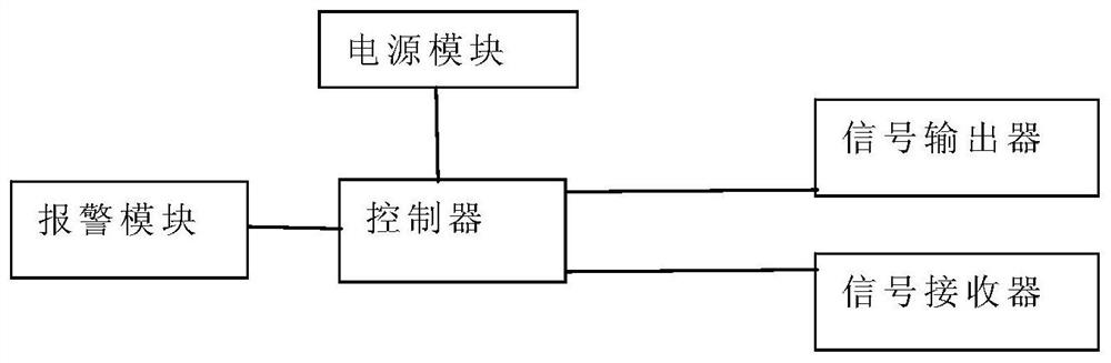
[0029] Please refer to figure 1 , this embodiment provides a cable core identification device, including:

[0030] Circuit board as controller, red light-emitting diode, electromagnetic buzzer, integrated power module, button battery, lead wire, secondary insulation clamp, secondary line pin. This is achieved through the following technical solutions:

[0031] The red light-emitting diode is fixed on the end of the circuit board, the electromagnetic buzzer is adjacent to the red light-emitting diode, and the machine red light-emitting diode and the buzzer are both electrically connected to the circuit board. Four button batteries are installed on the back of the circuit board as the power supply, and the battery installation module is connected to the integrated power module through wire welding, and the integrated power module acts as a voltage stabilizer. The secondary insulating wire clip and the secondary wire pin are welded on the circuit board through lead wires. Sele...

Embodiment 2

[0034] This embodiment provides a cable core identification method, including the following steps:

[0035] S 1. Select a wire core with cleaned wire number from the cable to be tested as the common core.

[0036] S2. Short-circuit the core to be identified with the common core at one end of the cable to be tested.

[0037] S3. At the other end of the cable to be tested, connect the common core of the signal transmitter, and use the signal receiver to randomly connect the cores other than the common core.

[0038] S4. The signal receiver triggers the controller to send a detection signal after changing the connected wire core each time. The controller sends a detection signal through the signal transmitter, and if the controller receives the detection signal through the signal receiver, it determines that the core currently connected to the signal receiver is the core to be identified. The controller sends a lighting signal to the red LED and sends a start signal to the buzz...


PUM


Abstract

The invention provides a cable core identification device and method. The device comprises a controller, a signal transmitter, a signal receiver and an alarm module, wherein the signal transmitter, the signal receiver and the alarm module are electrically connected with the controller; and the signal transmitter adopts an insulating clamp, and the signal receiver adopts a contact pin. The device is easy to operate and convenient to carry, the needed cable core can be identified by connecting different cable cores of a secondary cable, the identification result is more reliable by using two identification modes of light and voice, the structure is simple and easy to manufacture, external equipment is not needed, carrying is convenient, the checking accuracy of the secondary cable core can be greatly improved, moreover, the time for troubleshooting wrong wiring is shortened, and the stability and reliability of power supply are ensured. Meanwhile, the operation safety of equipment is guaranteed, unnecessary damage is avoided, the situation of wrong wiring is effectively prevented, and the safety of workers is guaranteed.

Description

technical field [0001] The invention belongs to the technical field of cable detection, and in particular relates to a cable core identification device and method. Background technique [0002] In recent years, with the development of electric power construction, a large number of new smart substations are under construction and old substations are being upgraded. During the construction of the substation, it is necessary to lay a large number of secondary cables. The length of the secondary cables ranges from 20 meters to 150 meters, and several to dozens of cables must be laid at the same electrical interval at the same time. This is a big problem at this time. It is the core check of the secondary cable. [0003] At present, the commonly used checking methods mainly include the following: 1. Check the wire number of the cable core: However, there are many problems with cables of different manufacturers and different qualities. In the case of inconsistent wire numbers, t...

Claims


Application Information

Patent Timeline
Patent Type & Authority Applications(China)
IPC IPC(8): G01R31/60G08B7/06
CPCG01R31/60G08B7/06
Inventor 王占德吕俊琪杜文一李盼盼马钰峰赵强石奇凡郭俊辰田东旭
Owner 国网山东省电力公司肥城市供电公司
Why Eureka
Try Eureka