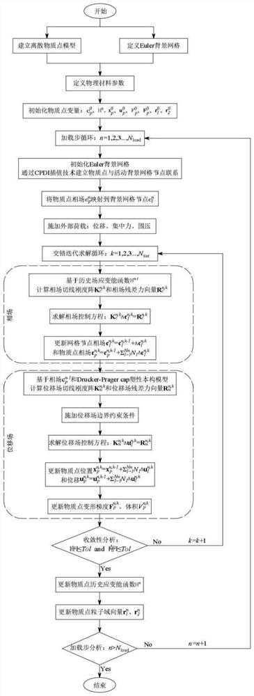
Phase field material point method for large deformation fracture analysis of rock-soil structure
A technology of large deformation and material point, applied in the field of computational mechanics, to overcome the incompleteness of complex mechanical behavior, reduce complexity, and simplify complexity
- Summary
- Abstract
- Description
- Claims
- Application Information
AI Technical Summary
Problems solved by technology
Method used
Image
Examples
Embodiment 1
[0178] (1) Embodiment 1: single opening plate tensile failure test (attached Figure 6-8 )
[0179] Embodiment 1 is a standard numerical example for a single-opening plate tensile failure experiment, and its structural dimensions and boundary conditions are as follows Figure 6 shown. The square plate was discretized into 249,000 material points, and the corresponding background grid was discretized into 255×255 four-node rectangular units with side length h=0.004mm, and 2×2 material points were set in each grid. Apply an incremental displacement Δu=10 to the upper boundary of the structure -6 mm, and the material parameters are shown in Table 1 below.
[0180] Table 1 Material parameter list of tensile failure test of single opening plate
[0181]
[0182] Figure 8 Shown is the phase field fracture nephogram of the single-opening plate tensile failure experiment at the loading displacement u=0.005525mm, u=0.0058mm and u=0.006mm, Figure 7 The comparison results of t...
Embodiment 2
[0183] (2) Example 2: Simulation of surrounding rock stress state and plastic deformation around the horizontal borehole in the plane strain domain (attached Figures 9 to 11 )
[0184] Example 2 is to verify the effectiveness and accuracy of the Drucker-Prager cap plastic constitutive model with smooth double yield surfaces, and simulate the stress state and plastic deformation behavior of the surrounding rock surrounding the horizontal borehole in the plane strain domain. The schematic diagram of the horizontal drilling structure size and boundary conditions in the quarter plane strain domain is shown in Fig. Figure 9 As shown in (a), the drilling radius R=107.95mm, the vertical confining pressure σ V =32.1Mpa, horizontal confining pressure σ H =9Mpa. In order to simulate the confining pressure stress state and plastic deformation behavior under different drilling pressures, we set four sets of drilling pressures P = 0, 4, 6, 8 MPa. The results of fine mesh division are...
Embodiment 3
[0190] (3) Embodiment 3: plane strain compression plastic fracture failure experiment (attached Figures 12 to 18 )
[0191] Example 3 is a plane strain compression experiment under different confining pressures to verify the elastoplastic fracture behavior of rock and soil materials. Figure 12 A schematic diagram of the structural size and boundary conditions of the rock specimen is given. The circle in the figure is the weakened area that guides the non-uniform deformation of the structure, and the cohesion strength C of all material points in the circle is set to be 98% of other areas. The specimen is discretized into 120×300 material points, and the corresponding background grid is discretized into 70×152 four-node rectangular units with side length h=0.5mm, and 2×2 material points are set in each grid. Set seven groups of boundary confining pressure σ c =5, 20, 40, 60, 100, 150, 200MPa, apply a downward displacement increment Δu=10 on the upper boundary of the structur...
PUM
| Property | Measurement | Unit |
|---|---|---|
| Young's modulus | aaaaa | aaaaa |
Abstract
Description
Claims
Application Information
 - R&D
- Intellectual Property
- Life Sciences
- Materials
- Tech Scout
- Unparalleled Data Quality
- Higher Quality Content
- 60% Fewer Hallucinations
Browse by: Latest US Patents, China's latest patents, Technical Efficacy Thesaurus, Application Domain, Technology Topic, Popular Technical Reports.
© 2025 PatSnap. All rights reserved.Legal|Privacy policy|Modern Slavery Act Transparency Statement|Sitemap|About US| Contact US: help@patsnap.com


