
Double-ridge horn antenna and electronic equipment

A ridge horn and antenna technology, applied in the field of double ridge horn antenna and electronic equipment

Pending Publication Date: 2021-09-07
SHENZHEN GONGJIN ELECTRONICS CO LTD
View PDF9 Cites 0 Cited by
  • Summary
  • Abstract
  • Description
  • Claims
  • Application Information

AI Technical Summary

Problems solved by technology

[0003] One of the purposes of the present invention is to provide a double-ridged horn antenna and electronic equipment to solve the problem of how to ensure the effective working bandwidth of the antenna and eliminate the current generated by high-order mode excitation caused by impedance mismatch. The problem

Method used

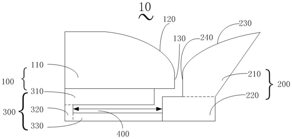
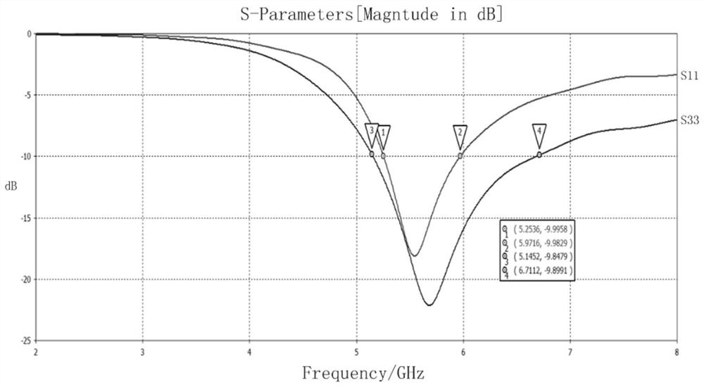

Image

  • Double-ridge horn antenna and electronic equipment
  • Double-ridge horn antenna and electronic equipment

Examples


Embodiment 1

[0027] Please refer to figure 1 , figure 1 A schematic block diagram of a structure of a double-ridged horn antenna provided by an embodiment of the present invention is shown.

[0028] The double-ridged horn antenna 10 includes: a first radiation oscillator 100, a second radiation oscillator 200, and an impedance transformation balun 300; the first radiation oscillator 100 includes a first part 310 and a first radiation part 110; the second radiation The vibrator 200 includes a second radiating part 210 and a connecting part 220; the impedance transformation balun 300 includes a first part 310, a second part 320 and a third part 330 that are sequentially connected and form a "U" shape, and the first part 310 deviates from One end of the third part 330 is connected to the first radiating part 110, and one end of the third part 330 away from the second part 320 is connected to the connecting part 220, and the first radiating part 110 is connected to the second The radiating p...

Embodiment 2

[0052] An embodiment of the present invention also provides an electronic device, the electronic device includes a PCB board and the double-ridged horn antenna as described in Embodiment 1 above, and the double-ridged antenna is arranged on the PCB board.

[0053] Specifically, the antenna is mainly produced by PCB processing technology, and the installation method of the double-ridge antenna on the PCB board is plug-in, mounting, or the structure is realized by metal stamping, or it is related to the use of the antenna. The PCB board of the whole machine circuit is merged into the whole main board, which improves the portability and ease of use of the whole electronic equipment and reduces the cost.

[0054] The electronic device provided by the embodiment of the present invention has the same technical features as the double-ridged horn antenna provided by the above-mentioned embodiment 1, so it can also solve the same technical problem and achieve the same technical effect, ...


PUM


Abstract

The embodiment of the invention discloses a double-ridge horn antenna and electronic equipment. The double-ridge horn antenna comprises a first radiation oscillator, a second radiation oscillator and an impedance conversion balun. The first radiation oscillator comprises a first part and a first radiation part. The second radiation oscillator comprises a connecting part and a second radiation part. The impedance conversion balun comprises a first part, a second part and a third part which are connected in sequence and form a U shape. The end, away from the third part, of the first part is connected with the first radiation part, and the end, away from the second part, of the third part is connected with the connecting part. The first radiation part and the second radiation part extend in the same direction. A gap is formed between the first radiation oscillator and the second radiation oscillator, and a signal is fed in from the gap. According to the double-ridge horn antenna and the electronic equipment, effective working bandwidth of the antenna can be ensured, and the current generated by high-order mode excitation caused by impedance mismatching can be eliminated.

Description

technical field [0001] The invention relates to the field of antennas, in particular to a double-ridge horn antenna and electronic equipment. Background technique [0002] Currently, most wireless electronic products use built-in antennas with a dipole topology. On the one hand, the bandwidth of the dipole antenna can only reach 15% usually, and there is a problem that the bandwidth is not enough to be effectively applied to the ultra-wideband communication system; on the other hand, although the impedance transformation balun structure of the dipole antenna can effectively suppress the high The current interference of the secondary mode signal greatly improves the radiation efficiency of the antenna. However, since the dipole antenna has an impedance transformation balun structure, the characteristic impedance of the signal channel is 50Ω, while the characteristic impedance of the dipole antenna is 73Ω, where the impedance The current generated by the high-order mode excit...

Claims


Application Information

Patent Timeline
IPC IPC(8): H01Q1/36H01Q13/02H01Q1/22H01Q13/10
CPCH01Q1/36H01Q13/0275H01Q13/10H01Q13/02H01Q1/2283Y02D30/70
Inventor 秦祥宏邓文朱余浩
Owner SHENZHEN GONGJIN ELECTRONICS CO LTD
Learn More