Low-profile low-loss Rotman lens

A low-loss, low-profile technology, used in electrical components, radiating element structures, antennas, etc., can solve the problems of high lens profile and large loss, and achieve the effects of mature and reliable technology, good consistency, and stable energy transmission.

Active Publication Date: 2021-09-07
SOUTHWEST CHINA RES INST OF ELECTRONICS EQUIP
View PDF11 Cites 0 Cited by
  • Summary
  • Abstract
  • Description
  • Claims
  • Application Information

AI Technical Summary

Problems solved by technology

[0005] The present invention aims to provide a low-profile and low-loss Rotman lens to solv

Method used


Image

  • Low-profile low-loss Rotman lens
  • Low-profile low-loss Rotman lens
  • Low-profile low-loss Rotman lens

Examples


Example Embodiment

[0033] Example

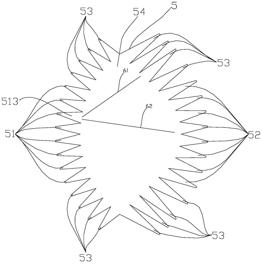
[0034] like figure 1Shown, the lens circuit 5 of traditional Rotman lens comprises input port 51, output port 52, vacant port 53 and lens body 54; Said vacant port 53 is positioned between input port 51 and output port 52; Traditional Rotman lens passes lens The body 54 completes the energy transmission between the input port 51 and the output port 52, and the energy transmission path satisfies the linear law of geometric optics, as shown in FIG. 3 . Taking the input port 513 as an example, the energy transmission path is similar to the first straight line 61 and the second straight line 62, causing part of the energy to be transmitted to the vacant port 53 area, resulting in energy loss.

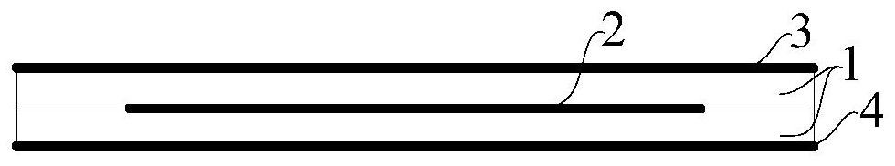
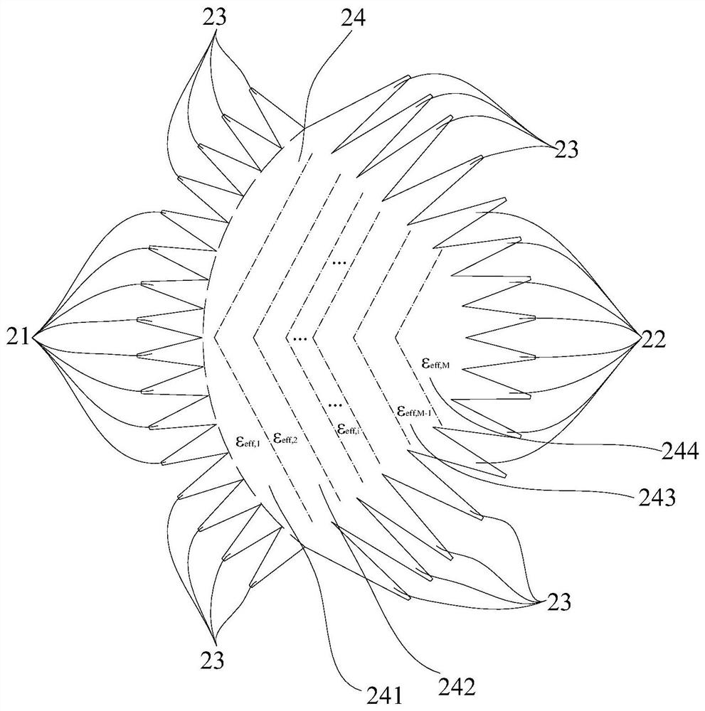
[0035] like figure 2 As shown, this embodiment proposes a low-profile and low-loss Rotman lens, including two layers of non-metallized dielectric substrate 1 and three layers of metallized copper-clad plane; the two-layer non-metallized dielectric substrate 1 is the uppe...


PUM


Abstract

The invention provides a low-profile and low-loss Rotman lens. The low-profile and low-loss Rotman lens comprises two layers of non-metallized dielectric substrates and three layers of metallized copper-clad planes; the two layers of non-metallized dielectric substrates are an upper layer non-metallized dielectric substrate and a lower layer non-metallized dielectric substrate; the three-layer metalized copper-clad plane comprises an upper layer metalized ground-clad plane, a middle layer printed metal plane lens and a lower layer metalized ground-clad plane; the middle-layer printed metal plane lens comprises a lens body, an input port and an output port which are located on the two sides of the lens body, and a vacant port located between the input port and the output port. The lens body is divided into M areas, and a non-metallized dielectric substrate area corresponding to each area has an equivalent relative dielectric constant partition design; and the input port, the output port and the vacant port are realized based on a strip line structure. The Rotman lens realized through lens body partition and the strip line structure has the characteristics of low profile and low loss.

Description

technical field [0001] The invention relates to the technical field of multi-beam forming networks, in particular to a low-profile and low-loss Rotman lens. Background technique [0002] In modern radar, communication and electronic warfare systems, antennas are often required to have multi-beam characteristics. Multi-beam antennas can form high-gain pencil beams to achieve long-distance work; multi-beam antennas can divide the single-antenna wide airspace into multiple pencil-shaped beams for simultaneous coverage, and use the amplitude information between multiple beams for direction finding, and then Realize long-distance detection in wide airspace; in addition, through the amplitude and phase control of the feed signal, the interference to the signal in the specified direction can also be realized, and the interference function can be realized. [0003] There are two types of antennas for multi-beam forming and scanning: phased array and multi-beam antennas. Phased arr...

Claims


Application Information

Patent Timeline
IPC IPC(8): H01Q15/02H01Q1/38
CPCH01Q15/02H01Q1/38
Inventor 李培李鹏杨培刚况泽灵罗旭刘颖李太波王菲王森张登材
Owner SOUTHWEST CHINA RES INST OF ELECTRONICS EQUIP
Why Eureka
Try Eureka