Calcaneus and talus prosthesis
A talus and prosthesis technology, applied in the direction of prosthesis, additive manufacturing, medical science, etc., can solve the problem of prolonged postoperative recovery time, difficulty in initial growth of calcaneal talus prosthesis, and easy occurrence of calcaneal talus prosthesis and preserved bone. Looseness etc.
- Summary
- Abstract
- Description
- Claims
- Application Information
AI Technical Summary
Problems solved by technology
Method used
Image
Examples
Embodiment 1
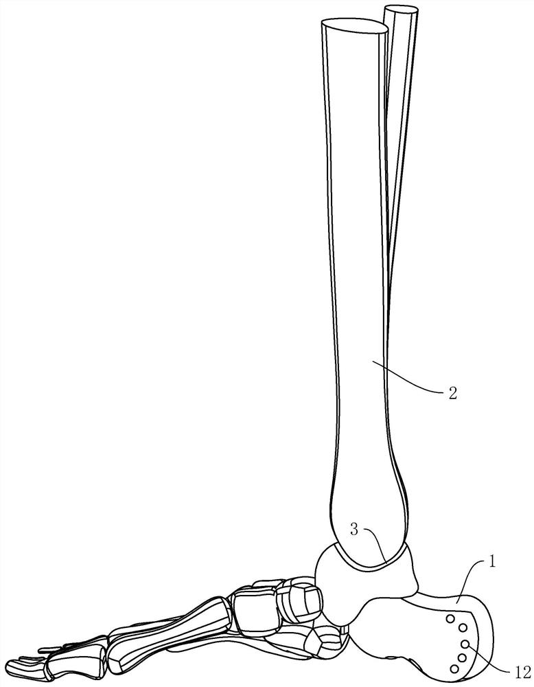
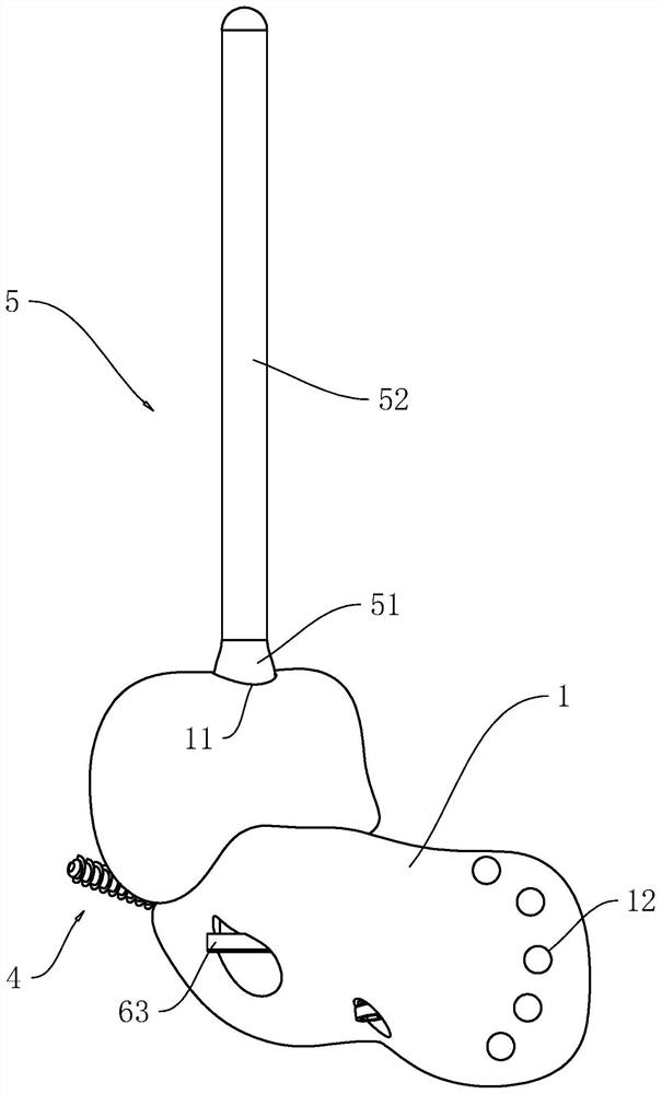
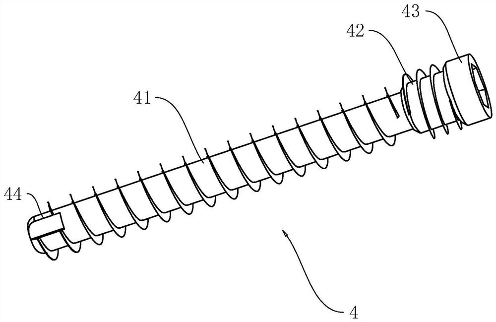
[0041] refer to figure 1 and figure 2 , the application provides a calcaneus and talus prosthesis. The calcaneus and talus prosthesis 1 has a fitting plate 3 corresponding to the end face of the retained bone 2, and the fitting plate 3 is made of a porous grid structure layer, wherein the porous grid structure layer The thickness of the porous mesh structure layer is 2mm, and the material of the porous mesh structure layer can be one of the porous structure of 3D printed bone trabecula, sprayed titanium / tantalum coating or hydroxyapatite coating; There is at least one fixation screw 4, and one end of the fixation screw 4 passes through the calcaneal and talar prosthesis 1 and extends into the retained bone 2. In the embodiment of the present application, there are three fixation screws 4. Of course, in other examples, the fixation screw 4 Can be provided with one or more; Offer at least one suturing hole 12 that is convenient to suturing ligament or soft tissue on the calcan...
Embodiment 2
[0051] refer to Figure 5 and Figure 6 , The difference between the second embodiment and the first embodiment is that: an adjustment member 7 is provided between the first part 51 and the second part 52; the adjustment member 7 includes a threaded rod 71 arranged between the first part 51 and the second part 52 , the threaded rod 71 and the second part 52 are threaded and coaxial, the end of the threaded rod 71 away from the second part 52 is fixedly connected with the end face of the first part 51 close to the second part 52, and the second part 52 is provided with a threaded rod 71 screwed into the threaded hole; the outer peripheral surface of the threaded rod 71 is provided with a protective sleeve 72, the protective sleeve 72 is slidingly connected to the second part 52, and the end of the protective sleeve 72 close to the first part 51 is connected to the end of the first part 51 close to the second part 52 The end surfaces are fixedly connected, and the end surface o...
Embodiment 3
[0054] refer to Figure 7 , The difference between the third embodiment and the first embodiment is that: an adjustment member 7 is provided between the first part 51 and the second part 52; the adjustment member 7 includes an adjustment rod 73 arranged between the first part 51 and the second part 52 , the adjusting rod 73 is slidingly connected and coaxial with the second part 52, the end of the adjusting rod 73 away from the second part 52 is fixedly connected with the end face of the first part 51 close to the second part 52, and the second part 52 is provided with an adjusting rod 73 Sliding chute 522; the adjustment member 7 includes a plurality of springs 74 uniformly arranged on the side of the adjustment rod 73 along the axial direction of the adjustment rod 73. In the embodiment of the present application, there are six springs 74, and two springs 74 are adjusted along the The axis of the rod 73 is arranged symmetrically; the spring 74 is arranged inside the adjustme...
PUM
| Property | Measurement | Unit |
|---|---|---|
| Thickness | aaaaa | aaaaa |
Abstract
Description
Claims
Application Information
 - R&D Engineer
- R&D Manager
- IP Professional
- Industry Leading Data Capabilities
- Powerful AI technology
- Patent DNA Extraction
Browse by: Latest US Patents, China's latest patents, Technical Efficacy Thesaurus, Application Domain, Technology Topic, Popular Technical Reports.
© 2024 PatSnap. All rights reserved.Legal|Privacy policy|Modern Slavery Act Transparency Statement|Sitemap|About US| Contact US: help@patsnap.com


