Motor shaft conveying line

A technology for motor shafts and conveyor lines, which is applied in the direction of conveyors, conveyor objects, transportation and packaging, etc., and can solve problems such as the inability to meet the production of different specifications of motor shafts, and the single production specification of motor shafts

Active Publication Date: 2021-09-10
常州市昌隆电机股份有限公司
View PDF7 Cites 2 Cited by
  • Summary
  • Abstract
  • Description
  • Claims
  • Application Information

AI Technical Summary

Problems solved by technology

[0004] In order to solve the problem that the current production line of automation equipment has a single motor shaft production specification and

Method used


Image

  • Motor shaft conveying line
  • Motor shaft conveying line
  • Motor shaft conveying line

Examples


Embodiment 1

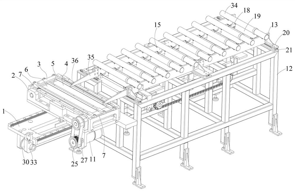
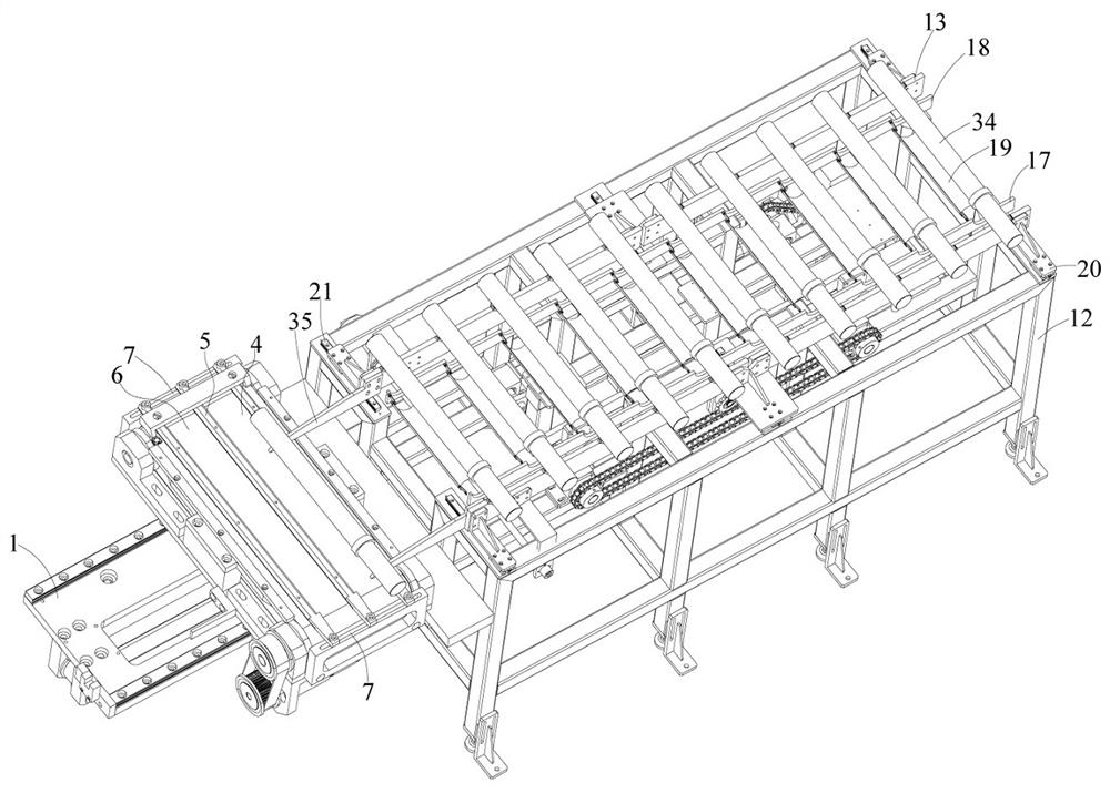
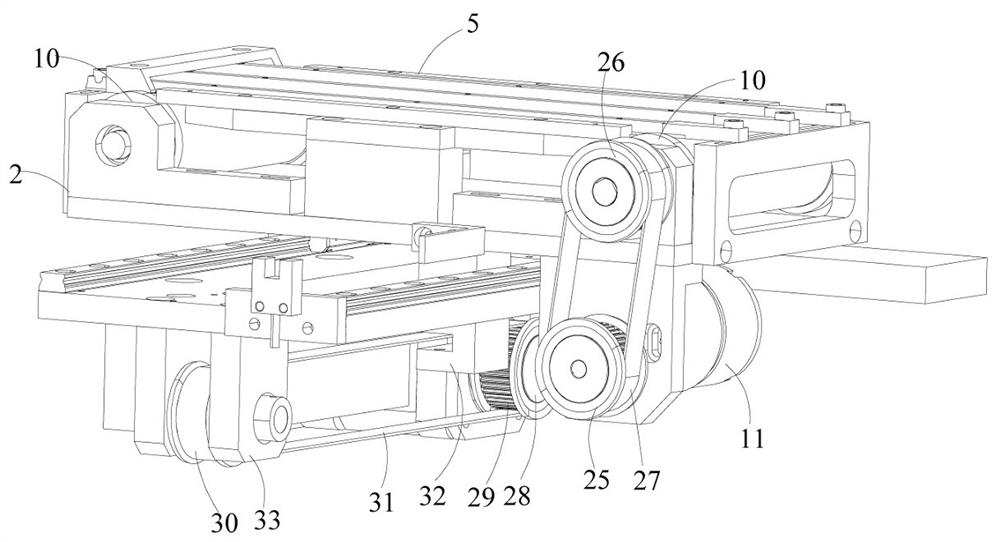
[0033] A motor shaft transmission line, such as Figure 1~7 As shown, it includes a mounting frame 1 fixedly arranged at one end of the conveying mechanism, a first bracket 2 slidably arranged on the mounting frame 1, a conveyor belt 4 rotatably arranged on the first bracket 2, and a conveyor belt 4 slidably arranged on the first An adjustment mechanism on a bracket 2 and a power mechanism for driving the first bracket 2 to slide; wherein the direction in which the power mechanism drives the first bracket 2 to slide is parallel to the direction in which the adjustment mechanism slides; the adjustment The mechanism includes a plurality of adjustment rods 5 , a placement cavity 6 is formed between two adjacent adjustment rods 5 , and the plurality of adjustment rods 5 are slidably arranged on the first bracket 2 for adjusting the width of the placement cavity 6 .

[0034] The adjustment mechanism also includes a second bracket 3 arranged at both ends of the first bracket 2 and a...


PUM


Abstract

The invention provides a motor shaft conveying line which comprises a mounting frame fixedly arranged at one end of a conveying mechanism, a first support arranged on the mounting frame in a sliding mode, a conveyor belt rotatably arranged on the first support, an adjusting mechanism arranged on the first support in a sliding mode and a power mechanism used for driving the first support to slide. According to the motor shaft conveying line, the structure is simple, the first support is arranged at one end of the conveying mechanism, a motor shaft rolls onto a containing cavity and is conveyed to the next procedure through the conveyor belt in the containing cavity, the size of the containing cavity can be adjusted, and conveying of motor shafts of different specifications is realized.

Description

technical field [0001] The invention relates to the technical field of motors, in particular to a motor shaft transmission line. Background technique [0002] Due to the rapid development of robots and electric vehicles, the demand for motors is increasing. The existing production of motors is labor-intensive, which leads to high labor costs for manufacturers, and manual operations often lead to difficult quality control and production. The problem of inefficiency. [0003] However, the motor shaft is one of the important parts of the motor. In the automatic production process, the existing equipment can only meet the production of a single motor shaft, but cannot meet the production of motor shafts of different specifications. Contents of the invention [0004] In order to solve the problem that the current production line of automation equipment has a single motor shaft production specification and cannot satisfy the production of motor shafts of different specificatio...

Claims


Application Information

Patent Timeline
IPC IPC(8): B05C3/10B05C11/10B05C13/02B65G23/04B65G23/22B65G23/24B65G47/74
CPCB05C3/10B05C13/02B05C11/1039B65G23/04B65G23/22B65G23/24B65G47/74B65G2201/0232
Inventor 王建南高昱黄丽萍王璐颖
Owner 常州市昌隆电机股份有限公司
Why Eureka
Try Eureka