
Method for automatically extracting working face area image of constructional engineering

A construction engineering, automatic extraction technology, applied in the field of construction site image processing, can solve the problems of lack of visual information, usability discount, physical meaning, unclear spatial meaning, etc.

Pending Publication Date: 2021-09-10
NANJING INST OF TECH
View PDF1 Cites 1 Cited by
  • Summary
  • Abstract
  • Description
  • Claims
  • Application Information

AI Technical Summary

Problems solved by technology

These commonly used single-photo-based image segmentation methods rely on the characteristics of the target such as color, edge, and texture; the identified areas have unclear physical and spatial meanings, and misjudgments are inevitable
When in a complex engineering scene, the features and boundaries of the working surface are not clear. It is often difficult to effectively identify the image of the "working surface area" as the area of ​​interest.
[0003] After the application of 3D modeling based on photos is becoming more and more widespread, it is also a more effective image of the working face area to perform 3D modeling on the scene photos and fuse the plane images of the working face to generate the orthophoto image of the "working face area". However, in the process of multi-image fusion, the 3D scene in the working surface area is often distorted and deformed due to the small number of images and the inability to model the masked area. At this time, the orthophoto is generated through the 3D model The image of the working face area obtained by projection method has a large amount of missing visual information, even if the manual method is used, it is difficult to read the working face; for the automatic recognition of machine vision, this kind of working face orthoimage Availability is also greatly reduced

Method used


Image

  • Method for automatically extracting working face area image of constructional engineering
  • Method for automatically extracting working face area image of constructional engineering
  • Method for automatically extracting working face area image of constructional engineering

Examples


Embodiment Construction

[0050] The present invention will be further described below in conjunction with the accompanying drawings and specific embodiments, but the protection scope of the present invention is not limited thereto.

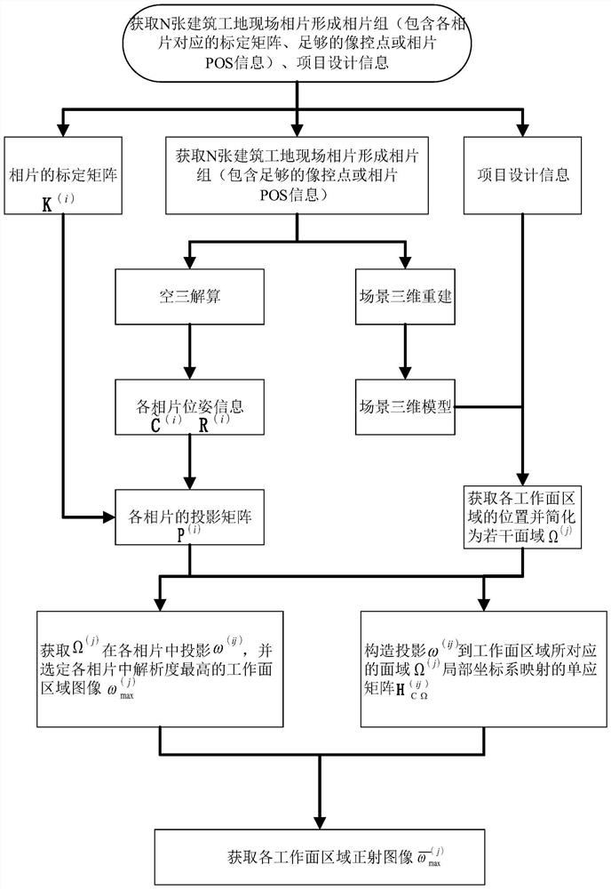
[0051] Such as figure 1 , a method for automatically extracting images of construction engineering working face regions, comprising the following steps:

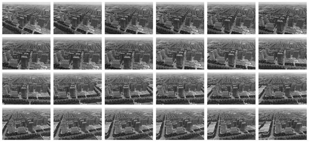
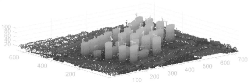
[0052] Step (1), obtain N construction site photos to form a photo group, and calculate the projection center position of each photo by performing aerial triangulation analysis on the photo group and the rotation matrix R from the world coordinate system to the photo coordinate system (i) , to reconstruct the three-dimensional model of the scene; wherein, the superscript (i) represents the i-th photo, i=1, 2, ..., N. Aerial triangulation analysis and 3D reconstruction can be completed by commercial software for image 3D reconstruction (such as Dajiang Zhitu, Smart3D, etc.). At present, the calculation core of this ki...


PUM


Abstract

A method for automatically extracting a working face area image of constructional engineering comprises the steps of obtaining N building site photos to form a photo group, conducting aerial triangulation analysis on the photo group to obtain pose information of the photos, then reconstructing a scene three-dimensional model, and obtaining a projection matrix P<(i)> based on the pose information of the photos and a calibration matrix K<(i)> of the photos; according to the point cloud and project design information of the scene three-dimensional model, obtaining the positions of M working face areas, and obtaining a face domain Omega<(j)> corresponding to the M working face areas; in the N photos, projecting the Omega<(j)> through the projection matrix P<(i)> to obtain a projection area omega (ij) on the ith photo, and finding out the projection omega<(j)>max with the highest Omega<(j)> resolution from the projection areas of the N photos, and converting omega<(j)>max into a working face area orthographic image omega(-)<(j)>max by using the homography matrix H<(ij)>C[Omega] of the image under the Omega<(j)> local coordinate system derived fromomega<(j)>max by the invention. The extraction method can automatically extract a working face area image from a single photo with exact physical significance and high fidelity.

Description

technical field [0001] The invention relates to the technical field of construction site image processing, in particular to a method for automatically extracting images of construction work face regions. Background technique [0002] As the cost of digital imaging equipment is getting lower and lower, surveillance photos of various scenes are becoming more and more common. This provides us with a data-level basis for automated information extraction and processing through machine vision technology. In many cases, the object of image analysis is not the entire photo, but some areas in it, which can be called "regions of interest". During the main construction phase of a building project, the main "area of ​​interest" is the floor working face. The working surface indicates the size of the space where certain workers may be placed on the construction object to operate or arrange construction machinery, so the working surface is used to reflect the state of the construction p...

Claims


Application Information

Patent Timeline
IPC IPC(8): G06T17/00G06T7/70G06T7/62
CPCG06T17/00G06T7/70G06T7/62G06T2207/10004
Inventor 李成涛陈立姚楠马文刚胡世翔黄传峰林敏肖仪清李朝潘大荣朱玉琴丛菱施佳琳王一笑
Owner NANJING INST OF TECH
Learn More