Passive residual heat removal system based on coupling heat pipe technology

A passive waste heat and heat pipe technology, applied in nuclear power generation, greenhouse gas reduction, climate sustainability, etc., can solve the problems of maintaining the operating temperature of thermoelectric generators, limited thermoelectric conversion efficiency of thermoelectric power generation, and inability to use heat directly

Pending Publication Date: 2021-09-10
XI AN JIAOTONG UNIV
View PDF4 Cites 0 Cited by
  • Summary
  • Abstract
  • Description
  • Claims
  • Application Information

AI Technical Summary

Problems solved by technology

However, due to the limited thermoelectric conversion efficiency of thermoelectric power generation, most of the heat cannot be used directly, and the excess heat needs to be taken away in time to maintain the working...

Method used


Image

  • Passive residual heat removal system based on coupling heat pipe technology

Examples


Embodiment Construction

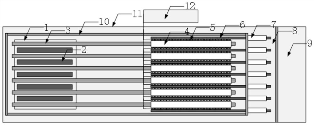
[0020] The present invention will be described in further detail below in conjunction with the accompanying drawings and specific embodiments.

[0021] Such as figure 1 As shown, a passive waste heat removal system coupled with heat pipe technology in the present invention consists of a base 1, a fuel rod 2, a first-stage heat pipe 3, a base 4, a TEG thermoelectric power generation device 5, a second-stage heat pipe 6, and fins 7 , the seawater 8 between the inner and outer shells, the seawater 9 outside the submersible, the inner shell 10 and the outer shell 11; wherein the base 1, the fuel rod 2, the first stage heat pipe 3, the base body 4, the TEG thermoelectric power generation device 5, The heat absorption area of ​​the second-stage heat pipe 6 is located in the inner shell 10, and the heat release area and the fins 7 of the second-stage heat pipe 6 are located between the inner shell 10 and the outer shell 11;

[0022] The pedestal 1 is located in the core and plays a ...


PUM


Abstract

A residual heat direct removal system based on a coupling heat pipe technology comprises two stages of heat pipes. A heat absorption area of the first-stage heat pipe is inserted into a heat conduction base of a nuclear reactor core, heat exchange is carried out between the heat absorption area of the first-stage heat pipe and fuel rods distributed in the base in a staggered mode, and heat is transmitted to a thermoelectric power generation device arranged in a heat release area of the heat pipe through the heat pipe, and the heat pipe serves as a hot end of the thermoelectric power generation device. A heat absorption area of the second-stage heat pipe is arranged at the cold end of the thermoelectric power generation device to take away residue heat which is not utilized in the thermoelectric conversion process, a heat release area of the second-stage heat pipe is arranged in the middle of a double-layer shell, and heat is transferred to seawater between the inner shell and the outer shell from the heat release area in a convective heat transfer mode. An efficient heat pipe technology is adopted, the energy transmission and cooling efficiency is improved while it is guaranteed that the structure is compact, safe and reliable, and the conversion power is improved. The safety and the stability of an underwater unmanned underwater vehicle are greatly improved. The passiveness of the system is guaranteed, the structure is closed in the whole process and is safe and stable, no impurity enters the system, and the system is pollution-free and corrosion-resistant.

Description

technical field [0001] The invention relates to a passive waste heat discharge system, in particular to a passive waste heat discharge system coupled with heat pipe technology. Background technique [0002] The silent passive heat transfer and energy conversion system uses heat pipe technology to obtain the heat generated by a small nuclear reactor, transports the energy from the core to the thermoelectric generator through the heat pipe as a heat source for thermoelectric power generation, and then converts the heat energy into electrical energy through the thermoelectric generator. Underwater unmanned submersibles provide power. However, due to the limited thermoelectric conversion efficiency of thermoelectric power generation, most of the heat cannot be used directly, and the excess heat needs to be taken away in time to maintain the working temperature of the thermoelectric generator. At the same time, the underwater submersible has limited internal space and a complex ...

Claims


Application Information

Patent Timeline
IPC IPC(8): G21C15/18G21C15/257
CPCG21C15/18G21C15/257Y02E30/30
Inventor 王进仕杨青凌马自强陈伟雄严俊杰王成龙秋穗正
Owner XI AN JIAOTONG UNIV
Why Eureka
Try Eureka