
Clock system with synchronization function and synchronization implementation method thereof

A technology of clock system and synchronization function, applied in the direction of automatic power control, electrical components, etc., can solve problems such as inability, multiplexing, occupying circuit board area/large microwave module volume, etc.

Active Publication Date: 2021-09-10
CHINA ELECTRONIS TECH INSTR CO LTD
View PDF7 Cites 3 Cited by
  • Summary
  • Abstract
  • Description
  • Claims
  • Application Information

AI Technical Summary

Problems solved by technology

[0004] Since the above traditional synchronization schemes and various internal clock generation schemes are only based on the needs at the time, they are combined to form a temporary solution, which cannot be reused in other occasions, and there are circuit boards occupied in actual applications. The area / microwave module is characterized by large volume, heavy weight, and high cost, so a simple, economical, and reusable implementation that can efficiently integrate time-base synchronization and internal clock generation is required

Method used


Image

  • Clock system with synchronization function and synchronization implementation method thereof
  • Clock system with synchronization function and synchronization implementation method thereof
  • Clock system with synchronization function and synchronization implementation method thereof

Examples


Embodiment Construction

[0040] The following will clearly and completely describe the technical solutions in the embodiments of the present invention with reference to the drawings in the embodiments of the present invention.

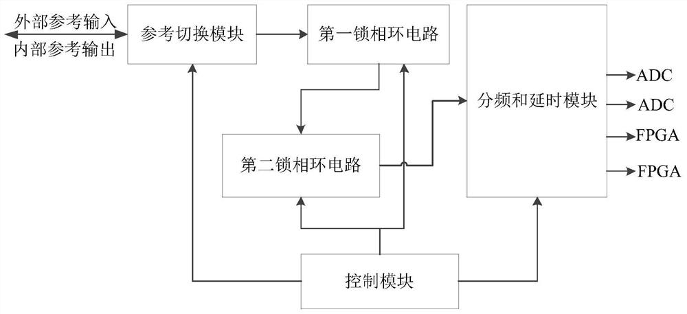
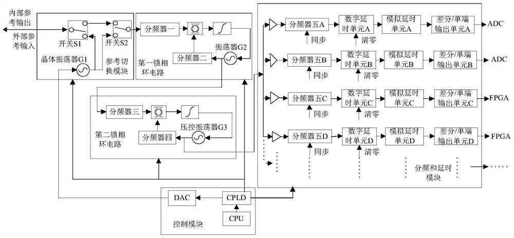
[0041] The invention provides a clock system with synchronization function, such as figure 1 and figure 2 As shown, it includes: a reference switching module, a first phase-locked loop circuit, a second phase-locked loop circuit, a frequency division and delay module and a control module.

[0042] 1. Reference switching module

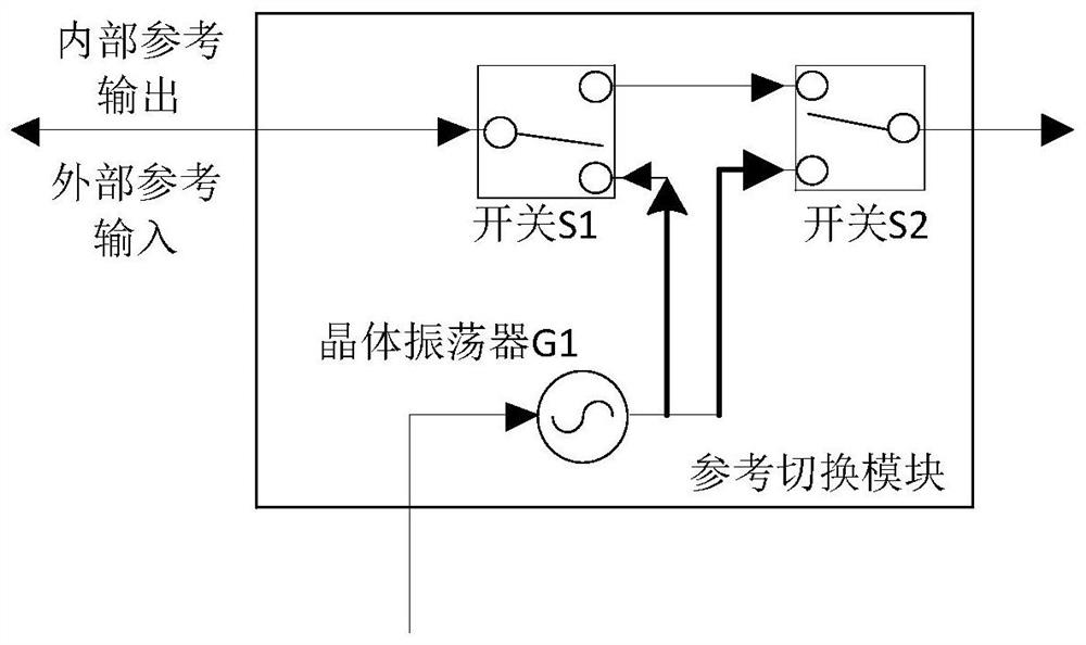
[0043] The reference switching module is used to switch internal and external reference signals (such as internally generated or externally provided 10MHz reference signal), and when using the internal reference signal, output the internal reference signal for external use.

[0044] Specifically, such as image 3 As shown, the reference switching module includes a switch S1, a switch S2 and a 10MHz constant temperature crystal oscillator G1. One end ...


PUM


Abstract

The invention discloses a clock system with a synchronization function and a synchronization implementation method thereof. The system comprises a reference switching module, a first phase-locked loop circuit, a second phase-locked loop circuit, a frequency division and delay module and a control module, wherein the reference switching module is used for switching internal and external reference signals; the first phase-locked loop circuit is connected with the reference switching module and is used for generating a reference signal with a higher frequency; the second phase-locked loop circuit is connected with the first phase-locked loop circuit and is used for generating a basic time base signal; the frequency division and delay module is connected with the second phase-locked loop circuit and is used for performing frequency division and delay processing on the basic time base signal and then outputting various types of clocks; and the control module is connected with the reference switching module, the first phase-locked loop circuit, the second phase-locked loop circuit and the frequency division and delay module, and is used for controlling and setting parameters. The system disclosed by the invention is simple in circuit design, flexible in programming, small in size, light in weight, low in cost, low in power consumption and easy to implement.

Description

technical field [0001] The invention relates to the field of clock signal processing, in particular to a clock system with a synchronization function and a synchronization realization method thereof. Background technique [0002] With the development of modern electronic technology (especially chip technology), the frequency band of modern test instruments is getting wider and wider, and has been extended from the radio frequency field to the microwave and millimeter wave field. As a category of modern testing instruments, portable instruments are especially suitable for on-site and field testing occasions such as modern mobile communications and wireless signal monitoring due to their small size, light weight, low power consumption, and portability. In some test occasions, the reference time base of the portable instrument needs to be synchronized with the time base of the signal under test or other test instruments, and there are also various clock generation requirements ...

Claims


Application Information

Patent Timeline
IPC IPC(8): H03L7/18
CPCH03L7/18
Inventor 肖江涛李柏林王晓王健张健苏勇辉
Owner CHINA ELECTRONIS TECH INSTR CO LTD
Learn More