Rolling system with efficient cleaning function

A clean and functional technology, applied in the field of aluminum sheet rolling, can solve the problems of cleaning dead angle, complex structure, lack of material surface impurities, oil stain cleaning function, etc.

Pending Publication Date: 2021-09-14
LUOYANG WANJI ALUMINUM PROCESSING CO LTD
View PDF16 Cites 7 Cited by
  • Summary
  • Abstract
  • Description
  • Claims
  • Application Information

AI Technical Summary

Problems solved by technology

The defects of this device are mainly manifested in: 1. When the roll surface cleaning device cleans the roll, the lateral moving speed of the wiper is a fixed speed, which does not match the linear speed of the roll. When the rolling speed changes, the grinding of the roll surface is uneven, which is easy to cause There is a cleaning dead angle; 2. Since the upper and lower wipers are inclined, their own gravity will affect the driving force of the drive device.

Method used


Image

  • Rolling system with efficient cleaning function
  • Rolling system with efficient cleaning function
  • Rolling system with efficient cleaning function

Examples


Embodiment 1

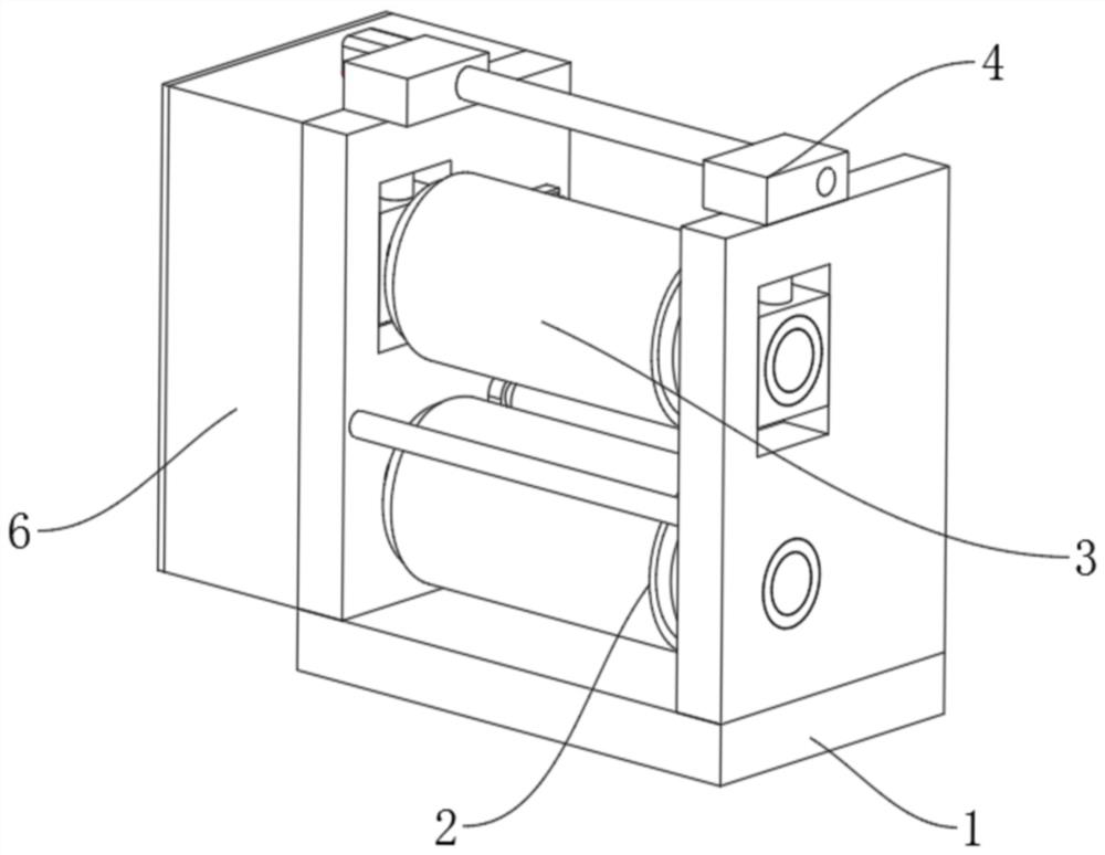
[0035] Embodiment one, such as Figure 1-6 As shown, a rolling system with high-efficiency cleaning function includes a frame 1, a lower roll 2, and an upper roll 3. A transmission box 6 is arranged on one side of the frame 1, and a horizontally arranged lower roll is fixedly installed on the inner side of the frame 1. 2. The front and rear of the lower roll 2 are provided with auxiliary support rolls 8 parallel to it. The roll 3 has the same diameter as the lower roll 2, and one end of the lower roll 2 and the upper roll 3 extends into the transmission box 6, and is connected with a transmission mechanism 5 that can make the lower roll 2 and the upper roll 3 synchronously and reversely rotate, and the transmission mechanism 5 is connected to the driving motor, and the rear sides of the lower roll 2 and the upper roll 3 are equipped with a cleaning mechanism 7, so that the material can be rolled through the upper roll 3 and the lower roll 2, and can also pass through the trans...

Embodiment 2

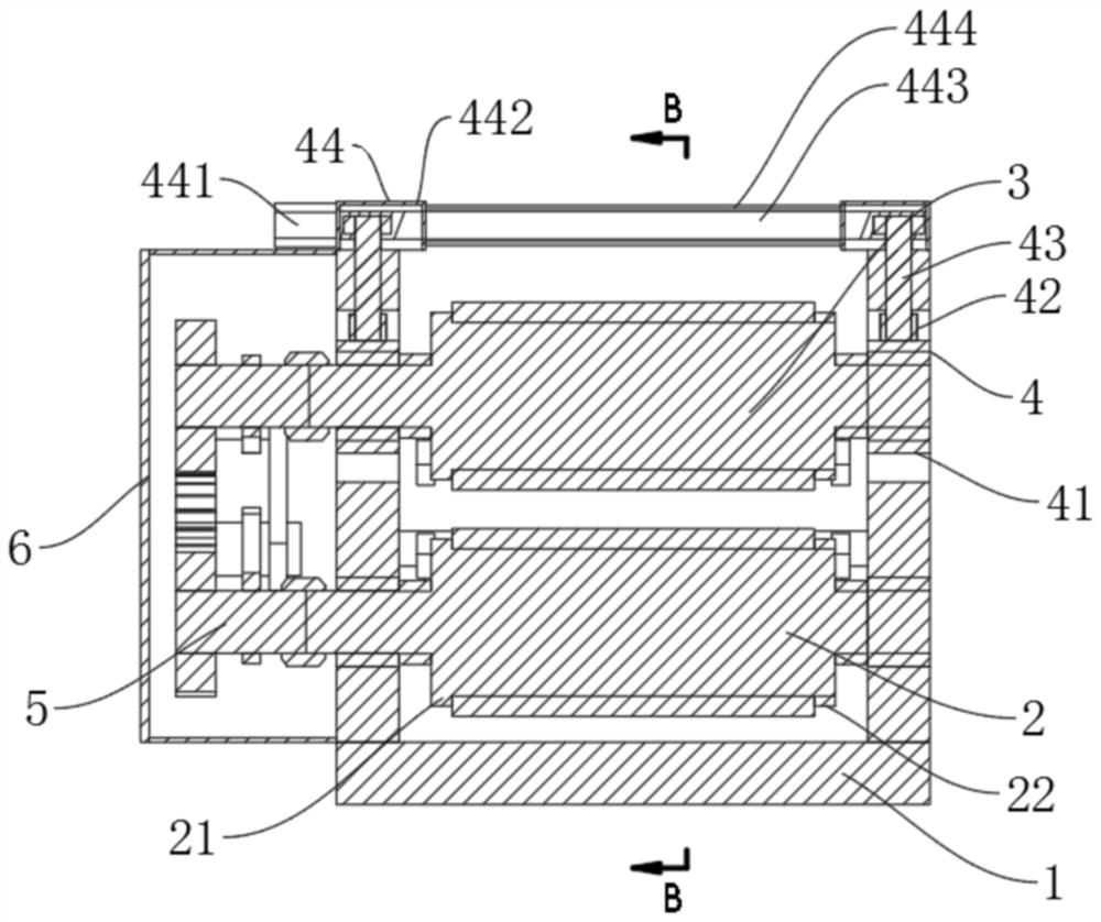
[0038] Embodiment two, on the basis of embodiment one, such as image 3 As shown, the two ends of the upper roll 3 are provided with an adjustment mechanism 4, the adjustment mechanism 4 includes a slide block 41, a threaded sleeve 42, and an adjustment shaft 43, and the inside of the two side walls of the frame 1 is provided with chutes arranged up and down. Slider 41 is slidably connected inside the groove, and slider 41 is connected with upper roller 3 through bearings. Threaded sleeve 42 is fixedly installed in the center of the top of slider 41, and a matching transmission screw is arranged inside the threaded sleeve 42. The transmission screw Set on the lower end of the adjustment shaft 43, the upper end of the adjustment shaft 43 extends out of the chute, and is connected with a drive assembly 44 that drives its rotation, so that the two adjustment shafts 43 can be driven to rotate by the drive assembly 44, and the adjustment shaft 43 rotates accordingly. , drive the th...

Embodiment 3

[0040] Embodiment three, on the basis of embodiment two, such as Figure 4 As shown, the fixed portion of the horizontal slide rail pair 76 in the cleaning mechanism 7 above is fixedly connected with the slide block 41 through the mounting bracket, and the central axis of the first cleaning roller 71 is on the same level as the central axis of the upper roller 3, so that The setting can make the cleaning mechanism 7 directly behind the upper roller 3 rise and fall with the lifting of the upper roller 3, and always ensure that the central axis of the first cleaning roller 71 is on the same level as the central axis of the upper roller 3, so that the first cleaning roller 71 The extrusion force on the upper roller 3 is completely a longitudinal force, the fixed part of the horizontal slide rail pair 76 in the cleaning mechanism 7 below is fixedly connected with the inner wall of the frame 1, and the central axis of the first cleaning roller 71 is in line with that of the lower ro...


PUM


Abstract

The invention relates to a rolling system with an efficient cleaning function, and relates to the technical field of aluminium plate rolling. The rolling system comprises a machine frame, a lower roller and an upper roller, the horizontally-arranged lower roller is fixedly installed on the inner side of the machine frame, auxiliary supporting rollers parallel to the lower roller are arranged in front of and behind the lower roller, the auxiliary supporting rollers are flush with the top of the lower roller, the upper roller parallel to the lower roller and adjustable in height is arranged above the lower roller, the upper roller and the lower roller are the same in diameter, and one end of the lower roller and one end of the upper roller extend into a transmission box. Materials with different thicknesses can be rolled by adjusting the up-down position of the upper roller, the function of sweeping impurities on the upper and lower surfaces of the lower roller, the upper roller and materials in a rolling brush mode can be achieved through a cleaning mechanism, a horizontal sliding rail pair can drive a first cleaning roller to move, and position adjusting equipment can drive a second driving box to further move a second cleaning roller, so that the condition that the cleaning effect is affected after the first cleaning roller and the second cleaning roller are used and abraded is avoided.

Description

technical field [0001] The invention relates to the technical field of aluminum plate rolling, in particular to a rolling system with efficient cleaning function. Background technique [0002] During the rolling process of traditional aluminum plate rolling mills, the rolls and roll surfaces will absorb a lot of sundries, oil stains, dust, etc., making the surface of the clean, smooth and shiny aluminum plate before rolling appear many stains, scratches, streaks, and the surface of the plate It is rough and loses its original luster; this problem leads to the next process, affects the appearance of the final product, and brings a series of problems for later product acceptance and factory inspection. The roll surface cleaning device of the existing rolling device is mainly composed of upper and lower wipers that are inclined to the rolling working surface of the roll and the corresponding driving device. When in use, the wiper is pushed to the roll surface and then moved lat...

Claims


Application Information

Patent Timeline
IPC IPC(8): B21B13/02B21B28/04B21B45/02B21B31/24
CPCB21B13/02B21B28/04B21B45/0275B21B31/24B21B2013/021
Inventor 邓涛李海强
Owner LUOYANG WANJI ALUMINUM PROCESSING CO LTD
Why Eureka
Try Eureka