
Muffle-free brazing furnace special for liquid cooling plate of power battery of new energy automobile

A new energy vehicle and power battery technology, applied in welding equipment, electric heating devices, metal processing equipment, etc., can solve the problems of affecting the brazing effect and brazing quality, high manufacturing cost, uneven heating, etc.

Pending Publication Date: 2021-09-14
纳百川控股有限公司 +1
View PDF7 Cites 0 Cited by
  • Summary
  • Abstract
  • Description
  • Claims
  • Application Information

AI Technical Summary

Problems solved by technology

The existing brazing furnace is equipped with a muffle in the hearth, the manufacturing cost is high, the use space is small, the heating device cannot directly heat the workpiece, the heating speed of the workpiece is slow, the heating is uneven, and the temperature detection effect is not accurate enough; the conveying device adopts conveying Roller or conveying mesh belt, the manufacturing cost of the conveying roller is high, it is easy to cause the workpiece to deviate or scratch during the conveying process, the conveying mesh belt is easy to take out the heat in the furnace during the conveying process, and the energy consumption is high; the nitrogen gas from the brazing The upper end of the welding area enters the furnace through the pipe, and the sealing effect is not good. Nitrogen is easily lost from the installation gap between the heating device and the furnace, which affects the level of pure nitrogen in the furnace, thereby affecting the brazing effect and brazing quality.

Method used


Image

  • Muffle-free brazing furnace special for liquid cooling plate of power battery of new energy automobile
  • Muffle-free brazing furnace special for liquid cooling plate of power battery of new energy automobile
  • Muffle-free brazing furnace special for liquid cooling plate of power battery of new energy automobile

Examples


Embodiment Construction

[0012] The specific content of the present invention will be described in detail below in conjunction with the accompanying drawings and specific embodiments.

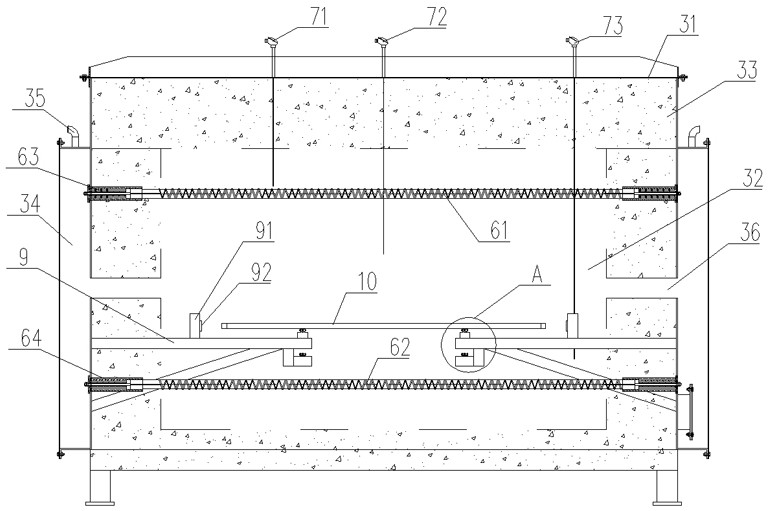
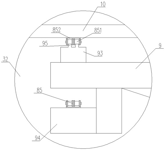
[0013] Such as figure 1 , figure 2 , image 3 , Figure 4 As shown, the special muffle-free brazing furnace for the liquid cold plate of the power battery of a new energy vehicle includes: a frame 1, on which the upper part area 2, the brazing area 3, and the air cooling area are sequentially arranged from front to back. Area 4 and lower part area 5, a chain circulation conveying device is arranged on the frame 1, and the chain circulating conveying device passes through the upper part area 2, the brazing area 3, the air cooling area 4 and the lower part area 5; The structure of the brazing zone 3 includes: a furnace body 31, a furnace 32 and a heating device arranged in the furnace body 31, the front end of the furnace 32 communicates with the upper part area 2, and the rear end of the furnace 32 communicates with...


PUM


Abstract

The invention discloses a muffle-free brazing furnace special for a power battery liquid cooling plate of a new energy automobile. The muffle-free brazing furnace is low in manufacturing cost and good in brazing effect and comprises a rack, a workpiece feeding area, a brazing area, an air cooling area and a workpiece discharging area are sequentially arranged on the rack from front to back, a chain circulating conveying device is arranged on the rack, the chain circulation conveying device penetrates through the workpiece feeding area, the brazing area, the air cooling area and the workpiece discharging area; and the brazing area structurally comprises a furnace body, a hearth and a heating device, the hearth and the heating device are arranged in the furnace body, the front end of the hearth communicates with the workpiece feeding area, the rear end of the hearth communicates with the air cooling area, nanometer heat preservation materials are arranged in the periphery of the furnace body, nitrogen cavities are formed in the left side and the right side of the exterior of the furnace body correspondingly, a brazing area nitrogen pipe is arranged at the upper end of each nitrogen cavity, a nitrogen inlet is formed in the bottom of each nitrogen cavity, and the nitrogen cavities communicate with the hearth through a nitrogen inlet.

Description

technical field [0001] The invention relates to a brazing furnace, in particular to a special muffle-free brazing furnace for a new energy vehicle power battery liquid cold plate. Background technique [0002] The liquid cold plate of the new energy vehicle power battery needs to use a brazing furnace in the process of processing to effectively connect the product. The brazing furnace uses the characteristic that the melting point of the solder alloy is lower than that of the metal material for welding. The brazing filler metal is usually placed near or inside the welding surface of the parts to be connected, and aluminum brazing flux is coated between the parts and the welding surface and on the surface, and the parts are heated under the protection of a certain inert gas until the brazing alloy melts and the metal of the parts does not melt temperature. The brazing flux breaks the oxide film of the metal material, allowing the surface diffusion between the molten metal a...

Claims


Application Information

Patent Timeline
IPC IPC(8): B23K3/00B23K3/04B23K3/08
CPCB23K3/00B23K3/04B23K3/08
Inventor 陈荣贤史定春
Owner 纳百川控股有限公司
Learn More