Hydrogen conveying system for hydrogenation vehicle

A delivery system, hydrogen technology, applied in pipeline systems, fixed-capacity gas storage tanks, container discharge methods, etc., can solve the problems of long filling time of hydrogen, excessive temperature, low reliability, etc.

Pending Publication Date: 2021-09-14
ADVANCED TECHNOLOGY & MATERIALS CO LTD +1
View PDF10 Cites 3 Cited by
  • Summary
  • Abstract
  • Description
  • Claims
  • Application Information

AI Technical Summary

Problems solved by technology

[0004] 1) During the hydrogenation process, due to the large pressure difference between the hydrogen storage tank in the hydrogenation machine and the on-board hydrogen storage bottle, the hydrogen flow rate in the hydrogen delivery pipeline increases first and then decreases. On the one hand, the on-board hydrogen storage bottle The temperature first rises rapidly and then decreases, which may cause the temperature to exceed the standard after filling the hydrogen storage bottle in the hydrogen refueling vehicle, and cause great wear and tear on the hydrogen delivery pipeline. On the other hand, the hydrogen in the hydrogen delivery pipeline The flow rate becomes smaller as the pressure difference between the hydrogen storage tank in the hydrogenation machine and the on-board hydrogen storage bottle becomes smaller, which makes it take longer to fill the hydrogen storage bottle in the hydrogenation vehicle
[0005] 2) The structural space in the hydrogenation machine is limited. When three hydrogen delivery pi

Method used


Image

  • Hydrogen conveying system for hydrogenation vehicle
  • Hydrogen conveying system for hydrogenation vehicle

Examples


Embodiment Construction

[0055] The technical solutions of the present invention will be clearly and completely described below in conjunction with the embodiments of the present invention. Apparently, the described embodiments are only some of the embodiments of the present invention, not all of them. Based on the embodiments of the present invention, all other embodiments obtained by persons of ordinary skill in the art without creative efforts fall within the protection scope of the present invention.

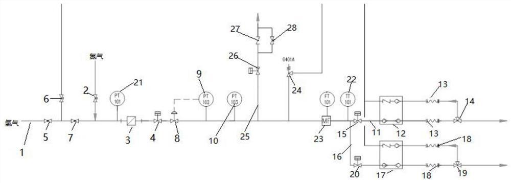
[0056] Such as figure 1 As shown, this embodiment provides a hydrogen delivery system for a hydrogenation vehicle, including a hydrogen delivery pipeline 1, a hydrogen delivery pressure adjustment assembly, a control unit (not shown in the figure) and a hydrogen outlet assembly. The control unit can use an independent unit, the PLC system in the hydrogenation machine can also be used as the control unit;

[0057] The hydrogen delivery pipeline 1 specifically adopts a single hydrogen delivery pipeli...


PUM


Abstract

The invention provides a hydrogen conveying system for a hydrogenation vehicle. The hydrogen conveying system comprises a hydrogen conveying pipeline, a hydrogen conveying pressure adjusting assembly and a control unit, wherein the hydrogen conveying pressure adjusting assembly is arranged on the hydrogen conveying pipeline; the hydrogen conveying pressure adjusting assembly is connected with the control unit; and the hydrogen conveying pressure adjusting assembly adjusts the hydrogen conveying pressure in the hydrogen conveying pipeline behind the hydrogen conveying pressure adjusting assembly according to a pressure curve set in the control unit. The problem that in the existing hydrogenation process, due to the fact that the pressure difference value between a hydrogen storage tank in a hydrogenation machine and a vehicle-mounted hydrogen storage bottle is large, the hydrogen flow in the hydrogen conveying pipeline is large and then small, the possibility that the temperature exceeds the standard after hydrogen is injected into the vehicle-mounted hydrogen storage bottle in the hydrogenation vehicle is likely to occur, and the hydrogen flow in the hydrogen conveying pipeline is reduced along with the reduction of the pressure difference between the hydrogen storage tank in the hydrogenation machine and the vehicle-mounted hydrogen storage bottle, so that the hydrogenation time in the hydrogen storage bottle in the hydrogenation vehicle is long is solved.

Description

technical field [0001] The invention belongs to a pipeline system of a hydrogenation machine in a hydrogenation station of a hydrogen fuel cell vehicle, and in particular relates to a hydrogen delivery system for a hydrogenation vehicle. Background technique [0002] Hydrogen energy and fuel cell technology, as important innovative technologies to promote low-carbon and environmentally friendly economic and social development, have reached a global consensus. Since 2016, with the growth of the domestic fuel cell vehicle market and the country's continuous introduction of industrial support policies, domestic demonstration hydrogen refueling stations have gradually begun to be built and operated. There are many types of hydrogenation vehicles for hydrogenation stations, such as logistics vehicles, buses, buses, etc.; hydrogenation pressure levels are 35MPa and 70MPa; because most of the vehicle-mounted hydrogen storage bottles of hydrogenation vehicles use aluminum liner fibe...

Claims


Application Information

Patent Timeline
IPC IPC(8): F17D1/04F17D3/01F17D5/00F17C7/00F17C13/04F17C13/00
CPCF17D1/04F17D3/01F17D5/00F17C7/00F17C13/04F17C13/00F17C2221/012F17C2270/0184F17C2265/06Y02E60/32Y02E60/34
Inventor 潘益锋何鹏赵英朋王凡张博平韶波
Owner ADVANCED TECHNOLOGY & MATERIALS CO LTD
Why Eureka
Try Eureka