Heat storage electric heating device adopting power frequency induction heating and manufacturing method

A technology of induction heating and heating circuit, applied in the fields of materials science, electromagnetism, and heat transfer, which can solve the problems of long heating time and so on.

Pending Publication Date: 2021-09-14
NANJING UNIV OF POSTS & TELECOMM
View PDF8 Cites 0 Cited by
  • Summary
  • Abstract
  • Description
  • Claims
  • Application Information

AI Technical Summary

Problems solved by technology

However, it can only be heated by high-frequency current, and the use of medium-high frequency electromagnetic induction heating requires the use of a relatively complex power frequency-medium high frequency conversion circuit. , storage, and release are easy to control, and the existing heat storage and electric heating devices still need to be improved

Method used


Image

  • Heat storage electric heating device adopting power frequency induction heating and manufacturing method
  • Heat storage electric heating device adopting power frequency induction heating and manufacturing method
  • Heat storage electric heating device adopting power frequency induction heating and manufacturing method

Examples


Embodiment 1

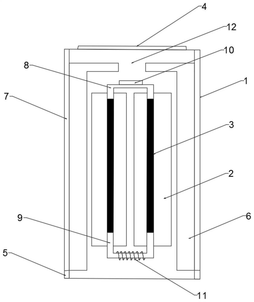
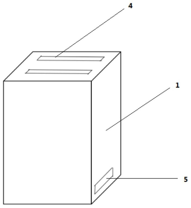
[0033] see figure 1 , this embodiment provides a heat storage electric heating device adopting power frequency induction heating, comprising a housing 1, an air outlet 4 is provided at the upper end of the housing 1, two air inlets 5 are provided at the lower end of the housing 1, and the outlet A plurality of ventilation channels 12 are formed between the tuyere 4 and the two air inlets 5, and a heating device and a plurality of heat storage structures 2 are arranged inside the casing 1, and the heating device includes two parallel cylindrical metal Rod 3, the upper ends of the two cylindrical metal rods 3 are connected by a first connector 8, the lower ends of the two cylindrical metal rods 3 are connected by a second connector 9, and the second connector 9 is wound There is a coil 11, the coil 11 is connected with a heating circuit, and two cylindrical metal rods 3 are connected with the first connecting body 8 and the second connecting body 9 to form a closed magnetic chan...

Embodiment 2

[0045] see figure 1 and 2 , the present embodiment provides a method for manufacturing a heat storage electric heating device using power frequency induction heating, the method comprising:

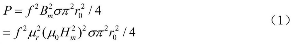
[0046] First of all, according to the characteristics of heat demand for household heating, the availability of using power frequency current to realize electricity-to-heat conversion is investigated. In normal use, the thermal storage electric heater chooses to heat during the valley electricity period at night, and the heating time is 8 hours, and the other 16 hours in a day are pure heat release time. For simplification, within 24 hours a day, the heater releases heat evenly, with a rated power of 1.6kW (the general heating area is 10-15m 2 ) electric heater as an example, the total heat required is Q=16×60×60×1600=92160kJ. Under the excitation of alternating current (frequency f), the unit length cylindrical metal rod (radius r 0 ) The average heating power of the metal is (neglec...


PUM


Abstract

The invention discloses a heat storage electric heating device adopting power frequency induction heating. The device is characterized in that an air outlet is formed in the upper end of a shell, two air inlets are formed in the lower end of the shell, a plurality of ventilation ducts are formed between the air outlet and the two air inlets, a heating device and a plurality of heat storage structures are arranged in the shell, the heating device comprises two cylindrical metal bars arranged in parallel, the upper ends of the two cylindrical metal bars are connected through a first connector, the lower ends of the two cylindrical metal bars are connected through a second connector, a coil is wound on the second connector and connected with a heating circuit, a capacitor is arranged on the heating circuit, the two cylindrical metal bars are connected with the first connector and the second connector to form a closed magnetic channel; the outer side wall of each cylindrical metal rod is provided with a heat storage structure, and each cylindrical metal rod and the corresponding heat storage structure form a heating body. The use effect of the device is improved, the service life of the heating device and the heat storage structure is prolonged, and the production cost is reduced.

Description

technical field [0001] The present invention relates to electromagnetism, heat transfer, and material science, in particular to a method of using power frequency current to generate eddy currents in metal rods with high magnetic permeability and high thermal conductivity to realize electricity-to-heat conversion and to heat heat storage materials more uniformly , Combined with thermal insulation material and ventilation holes, it is a heat storage electric heating device that effectively regulates heat generation, storage and release. Background technique [0002] Heat storage electric heaters store heat energy during the valley period of nighttime electricity load and use it for heating during the day, which can realize peak load shifting and valley filling of the power grid, improve the efficiency and utilization of power generation devices, and can make full use of nighttime valley power heating to save users' heating costs. However, the market share is low due to problem...

Claims


Application Information

Patent Timeline
Patent Type & Authority Applications(China)
IPC IPC(8): F24D13/00F24D15/02F24D19/10
CPCF24D13/00F24D15/02F24D19/1096
Inventor 陈将伟谷鑫倪思远蒋禧炀
Owner NANJING UNIV OF POSTS & TELECOMM
Why Eureka
Try Eureka