Wind tunnel test aircraft wing deformation full-field measurement method

A technology of wind tunnel test and measurement method, applied in the field of wind tunnel test, can solve the problems of sparse measurement data and low spatial resolution, etc.

Active Publication Date: 2021-09-14
中国空气动力研究与发展中心设备设计与测试技术研究所
View PDF18 Cites 3 Cited by
  • Summary
  • Abstract
  • Description
  • Claims
  • Application Information

AI Technical Summary

Problems solved by technology

[0005] The purpose of the present invention is to provide a full-field measurement method for wind tunnel test aircraft wing deformation, to solve the problem that the wind tunnel test aircraft wing deformation measurement technology in the prior art can only measure discrete points, and there are sparse measurement data and low spatial resolution. Low-level problems, to achieve dense, higher spatial resolution measurement data, to achieve the full-field measurement of aircraft wing deformation and the full-field measurement of the three-dimensional topography of the wing surface in the deformed state

Method used


Image

  • Wind tunnel test aircraft wing deformation full-field measurement method
  • Wind tunnel test aircraft wing deformation full-field measurement method
  • Wind tunnel test aircraft wing deformation full-field measurement method

Examples


Embodiment 1

[0092] A full-field measurement method for wind tunnel test aircraft wing deformation, comprising:

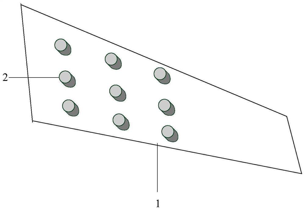
[0093] S1, making a spot pattern on the surface of the wing;

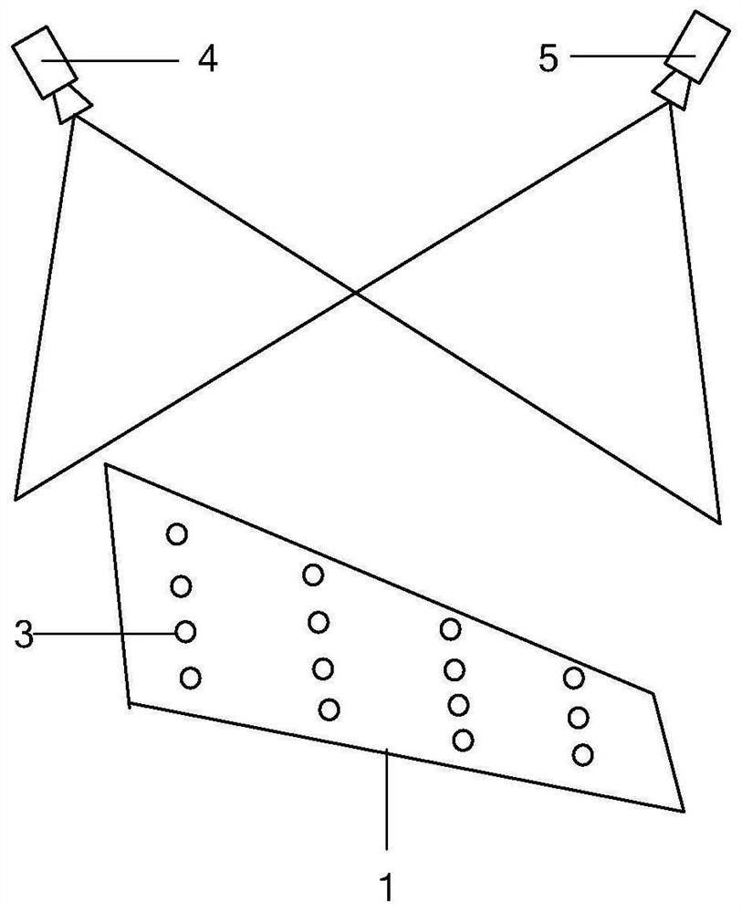
[0094] S2. Calibrate the stereo vision measurement system to obtain the internal parameter P of the camera a a , internal parameter P of camera b b , The calibration parameter P of the stereo vision measurement system s , the transformation matrix R that transforms the measurement coordinate system to the aircraft model coordinate system;

[0095] S3. According to the images taken by camera a and camera b before the blowing test and during the blowing test, a sequence of test images is obtained;

[0096] S4. Calculate the full-field measurement results of wing deformation based on the test image sequence.

[0097] The making method of spot pattern in the step S1 comprises:

[0098] S11. Make a number of holes with a diameter of 0.0001-1000mm, randomly distributed positions, and different sizes on the cloth / pape...

Embodiment 2

[0137] This embodiment takes a half-model test carried out in a research-type wind tunnel as an example.

[0138] Figure 9 A schematic diagram of the installation of the device for the half-model test of this embodiment is given. exist Figure 9 The meanings of the reference signs are as follows: the arrow 26 is the direction of the wind tunnel flow, and the arrow 27 is the test section of the wind tunnel. Facing the direction of the flow, the four walls of the test section of the wind tunnel are respectively named as the left wall 28, the lower wall 29, and the right wall. Wall 30, upper wall 31, the aircraft fuselage 11 is fixed on the middle part of the upper wall 31 of the test section, the surface of the wing 1 is drawn with a speckle pattern 6, and the camera a optical observation window 32 and the camera b optical observation window 33 are set in the middle section of the right wall 30, Camera a is set at the optical viewing window 32 of camera a, camera b is set at ...


PUM


Abstract

The invention discloses a wind tunnel test aircraft wing deformation full-field measurement method. The method comprises the following steps of making spot patterns on a surface of a wing; calibrating a stereoscopic vision measurement system to obtain an internal parameter Pa of the camera a, an internal parameter Pb of the camera b, a calibration parameter Ps of the stereoscopic vision measurement system and a transformation matrix R for converting a measurement coordinate system into an airplane model coordinate system; acquiring a test image sequence according to images shot by the camera a and the camera b before and during the blowing test; and calculating a wing deformation full-field measurement result based on the test image sequence. The method is used for solving problems of sparse measurement data, low spatial resolution and the like due to the fact that only discrete point measurement can be carried out in a wind tunnel test aircraft wing deformation measurement technology in the prior art, and dense measurement data with higher spatial resolution can be obtained; purposes of aircraft wing deformation full-field measurement and wing surface three-dimensional shape full-field measurement in the deformation state are achieved.

Description

technical field [0001] The invention relates to the field of wind tunnel tests, in particular to a full-field measurement method for wind tunnel test aircraft wing deformation. Background technique [0002] In the process of aircraft development, it is necessary to conduct scale model wind tunnel tests in the wind tunnel. In the wind tunnel test, since the aircraft model is not a rigid body, the aerodynamic load will cause a large deformation of the wing, which will affect the accuracy of the wind tunnel model test. Such as figure 1 As shown, the dotted line is the undeformed profile of the wing before the blowing test, and the solid line is the deformed profile of the wing in the blowing test. figure 1 For the front view of the aircraft. For this reason, it is necessary to accurately measure the aeroelastic deformation of the aircraft wing during the wind tunnel model test, so as to correct the measured data of the wind tunnel test later. In addition, with the adoption ...

Claims


Application Information

Patent Timeline
Patent Type & Authority Applications(China)
IPC IPC(8): G01M9/06G01M9/08G01B11/24G06T17/00
CPCG01M9/06G01M9/08G01B11/24G06T17/00Y02T90/00
Inventor 王斌张文清王众王强梁杰周鑫顾正华宋巍巍王盼
Owner 中国空气动力研究与发展中心设备设计与测试技术研究所
Why Eureka
Try Eureka