Shaft body cooling and heat dissipation device for CNC machine tool processing

A heat dissipation device and technology of CNC machine tools, which are applied in the direction of metal processing equipment, metal processing machinery parts, milling machine equipment, etc., can solve the problems of internal parts that are easy to burn, do not comply with energy saving and emission reduction, and affect the accuracy of milling cutters. Convenience, improved convenience, less usage

Active Publication Date: 2022-05-24
HANGZHOU VOCATIONAL & TECHN COLLEGE
View PDF0 Cites 0 Cited by
  • Summary
  • Abstract
  • Description
  • Claims
  • Application Information

AI Technical Summary

Problems solved by technology

[0004] The purpose of the present invention is to solve the problem that the milling cutter of the machine tool in the prior art is in a high-temperature working state for a long time, which will increase the energy consumption of the machine tool, affect the precision of the milling cutter, shorten the life of the milling cutter, and easily burn the internal parts due to sputtering of high-temperature debris. Parts are difficult to clean after high temperature adhesion. The traditional machine tool cooling device has a large mechanism, low efficiency, high energy consumption, serious consumption of cooling materials, and does not meet the requirements of energy saving and emission reduction. A CNC machine tool processing shaft is proposed. body cooling radiator

Method used


Image

  • Shaft body cooling and heat dissipation device for CNC machine tool processing
  • Shaft body cooling and heat dissipation device for CNC machine tool processing
  • Shaft body cooling and heat dissipation device for CNC machine tool processing

Examples


Embodiment 1

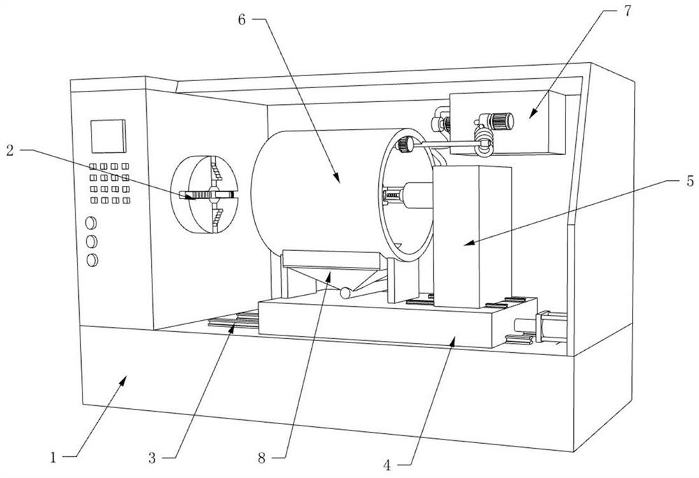
[0032] Reference Figure 1-2, the present embodiment relates to a CNC machine tool processing with shaft body cooling heat dissipation device, including the machine tool body 1, the machine tool body 1 is provided with a machining area, one end of the machining area is installed with a fixture 2, the other end is installed with a movable CNC milling cutter mechanism, CNC milling cutter mechanism is installed on the double guide rail 3 at the bottom of the machining area through the drive mechanism, CNC milling cutter mechanism comprising a moving base 4, milling cutter body 5, cooling heat dissipation mechanism 6, mobile base 4 through the cylinder drive, milling cutter body 5 and cooling heat dissipation mechanism are installed on the mobile base 4, Cooling heat dissipation mechanism is a transparent structure at both ends and located between the fixture 2 and the milling cutter body 5, the milling head of the milling cutter body 5 extends to the cooling cooling mechanism to proce...

Embodiment 2

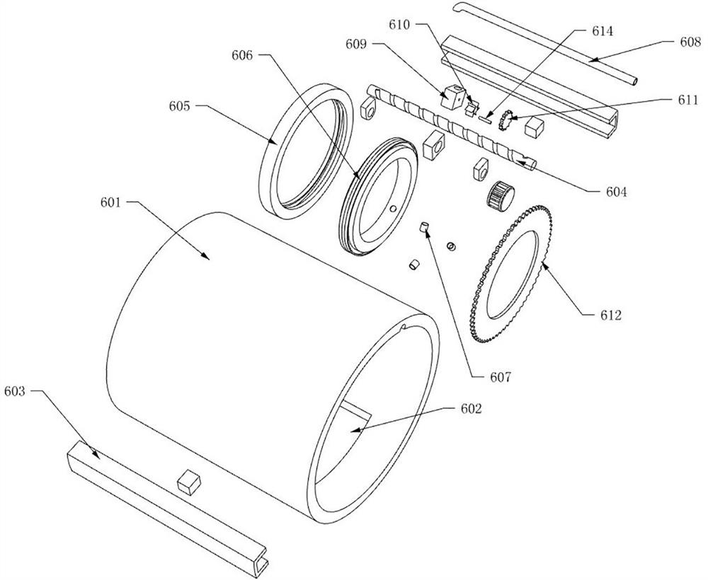
[0038] Reference Figure 3-6 , the present embodiment and the embodiment of a difference is that the structure of the cooling ring body is different, in the present embodiment, the cooling ring body includes the outer ring body 605 and the inner ring body 606, the inner ring body 606 rotation is installed on the inner ring wall of the outer ring body 605, the outer ring body 605 and the inner ring body 606 are hollow structures, and the hollow cavity of the two is interconnected to form a circular reservoir 613, the outer wall of the inner ring body 606 is fixed with a ring gear 612, and the drive mechanism is installed on the outer ring body 605, The drive mechanism is connected to the ring gear 612 transmission and drives the inner ring body 606 rotation, the drive mechanism is connected with the annular reservoir 613 and the metal tube 608.

[0039] The drive mechanism comprises housing 609, drive impeller 610, drive shaft 614 and drive gear 611, housing 609 is fixed mounted on th...

Embodiment 3

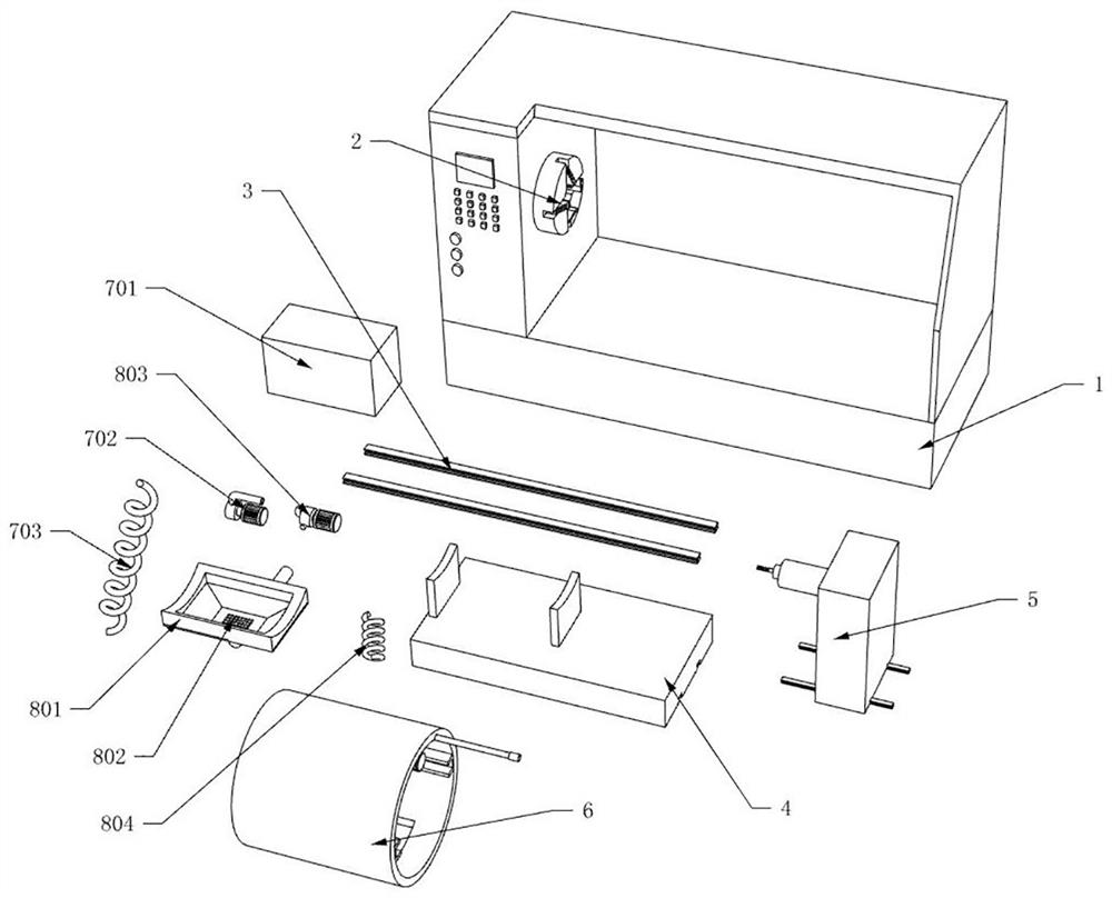
[0042] Reference Figure 7, the present embodiment and Example I and Example TWO are different in that the coolant circulation mechanism 8 is added to achieve the reuse of coolant, in the present embodiment, the bottom of the cooling and dissipation mechanism 6 is provided with a coolant circulation mechanism 8, the coolant circulation mechanism 8 comprises a collection tank 801, a filter core 802, a metal tube two 805, a spring hose two 804 and a return pump 803, a protective cover 601 is located at the bottom of the collection tank with an installation slot 602, the collection tank 801 is installed at the installation slot 602, The middle of the collection tank 801 is detachablely installed with a filter core 802, and the bottom of the collection tank 801 is connected to one end of the metal tube II 805, the other end of the metal tube II 805 is connected to the spring hose II 804, the spring hose II 804 is connected to the coolant tank 701 by the return pump 803.

[0043] In the...


PUM


Abstract

The invention discloses a shaft body cooling and heat dissipation device for numerical control machine tool processing, which relates to the field of numerical control machine tools, aiming at increasing the energy consumption of the machine tool when the milling cutter of the existing machine tool is in a high-temperature working state for a long time, affecting the precision of the milling cutter, and cooling A large amount of liquid is used, a large amount of waste liquid is discharged, and the problem of polluting the environment is proposed. The following plan is proposed, including the main body of the machine tool. CNC milling cutter mechanism, the CNC milling cutter mechanism includes a mobile base, a milling cutter body, a cooling and heat dissipation mechanism and a coolant storage device, the milling cutter head of the milling cutter body extends to the inside of the cooling and heat dissipation mechanism to clamp on the fixture The shaft is processed. The invention not only eliminates the high-temperature environment, reduces the high energy consumption burden of the machine tool, but also uses less coolant, can be recycled, reduces the discharge of waste liquid, and achieves the purpose of energy saving and emission reduction.

Description

Technical field [0001] The present invention relates to the field of CNC machine tools, in particular to a cnc machine tool processing shaft body cooling and heat dissipation device. Background [0002] CNC machine tool is short for digital control machine tool (Computer numerical control machine tools), is an automated machine tool equipped with a program control system. The control system can logically process the program having a control code or other symbolic instructions specified, and it is decoded, represented by coded numbers, and input to the numerical control device through the information carrier. After the operation processing, various control signals are issued by the numerical control device, the action of the machine tool is controlled, and the parts are automatically processed according to the shape and size required by the drawings. [0003] CNC machine tools in some shaft parts processing, often in the processing position of high temperature, sputtering high tem...

Claims


Application Information

Patent Timeline
Patent Type & Authority Patents(China)
IPC IPC(8): B23C3/00B23C9/00B23Q11/08B23Q11/10
CPCB23C9/00B23C3/00B23Q11/08B23Q11/10B23Q11/1069
Inventor 丁媛媛杨斌金俊吕哲翀金寅德
Owner HANGZHOU VOCATIONAL & TECHN COLLEGE
Why Eureka
Try Eureka