Rotary shearing mechanism and laying head for automatic fiber laying and forming

A technology of rotary shearing and rotary connection, which is applied to other household appliances, household appliances, household components, etc., which can solve problems such as overlapping and laying track boundary gaps, and achieve reduction of secondary processes, light materials, and improved laying The effect of molding quality

Pending Publication Date: 2021-09-17
HARBIN INST OF TECH
View PDF8 Cites 2 Cited by
  • Summary
  • Abstract
  • Description
  • Claims
  • Application Information

AI Technical Summary

Problems solved by technology

[0005] The purpose of the present invention is to solve the problem of gaps and overlapping defects at the boundary of

Method used


Image

  • Rotary shearing mechanism and laying head for automatic fiber laying and forming
  • Rotary shearing mechanism and laying head for automatic fiber laying and forming
  • Rotary shearing mechanism and laying head for automatic fiber laying and forming

Examples


specific Embodiment approach 1

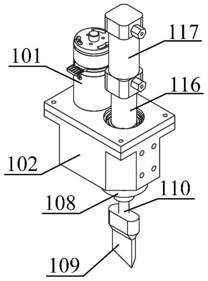
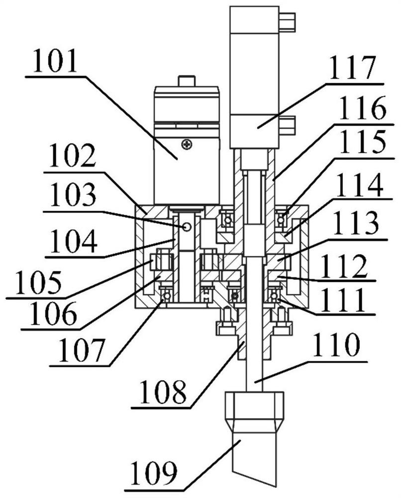
[0021] Specific implementation mode one: combine Figure 2-Figure 3 Describe the present embodiment, the rotary shearing mechanism, which includes a motor 101, a machine base 102, a flange shaft 104, a driving gear 105, a linear guide rail 108, a tool holder assembly 109, an extended stepped shaft 110, a driven gear 113, Cylinder sleeve 116 and cylinder 117; motor 101 casing is installed on the machine base 102, the end of the output shaft of the motor 101 is connected with the machine base 102 in rotation, the flange shaft 104 is fixedly set on the output shaft of the motor 101, the flange shaft 104 is fixedly connected with the driving gear 105, the flange shaft 104 and the driving gear 105 are arranged in the base 102, the housing of the cylinder 117 is fixedly connected with one end of the cylinder sleeve 116, and the piston rod of the cylinder 117 is connected with one end of the extended stepped shaft 110 Fixed connection, the tool holder assembly 109 is installed on the...

specific Embodiment approach 2

[0028] Specific implementation mode two: combination Figure 2-Figure 3 This embodiment is described. The rotary shearing mechanism described in this embodiment further includes a fixed key 103 , and the output shaft of the motor 101 is integrally connected with the flange shaft 104 through the fixed key 103 . Other compositions and connection methods are the same as those in Embodiment 1.

specific Embodiment approach 3

[0029] Specific implementation mode three: combination Figure 2-Figure 3Describe this embodiment, a rotary shearing mechanism described in this embodiment, the flange shaft 104 is a hollow shaft body, the flange of the flange shaft 104 is fixedly connected with the driving gear 105 by a plurality of bolts, and the flange shaft 104 The axis of is coincident with the central line of driving gear 105 and is set. Other compositions and connection methods are the same as those in Embodiment 1.


PUM


Abstract

The invention relates to a rotary shearing mechanism and a laying head for automatic fiber laying and forming, and aims to solve the problem that gaps and overlapping defects exist at the boundary of a laying track. The rotary shearing mechanism comprises a motor, a machine base, a flange shaft, a driving gear, a linear guide rail, a knife rest assembly, an extended stepped shaft, a driven gear, a air cylinder sleeve and an air cylinder, and the laying head comprises a rotary shearing mechanism, a re-conveying mechanism, a clamping mechanism, a first guide roller, a jumping roller, a second guide roller, an adapter plate, a third guide roller, a charging tray, a compression roller cylinder, a compression roller and a frame body. A motor shell is installed on the machine base, the flange shaft is fixedly installed on an output shaft of the motor in a sleeved mode and connected with the driving gear, a piston rod of the air cylinder is connected with one end of the extended stepped shaft, the knife rest assembly is installed at the other end of the extended stepped shaft, the other end of the air cylinder sleeve is fixedly connected with the driven gear, and the driving gear is meshed with the driven gear. The invention belongs to the technical field of automatic molding of matrix composite materials.

Description

technical field [0001] The invention relates to a rotary shearing mechanism and a laying head, in particular to a rotary shearing mechanism and a laying head for automatic wire laying and forming. The invention belongs to the technical field of automatic molding of matrix composite materials. Background technique [0002] The lightweight of high-end aerospace equipment has always been a major concern of the industry. Compared with traditional metal materials, advanced resin-based composite materials not only have the advantages of light weight, high strength, fatigue resistance, and corrosion resistance, but also integrate design and manufacturing. For forming complex components, it has become the fourth largest aerospace structural material after aluminum, steel and titanium. [0003] Regarding the automatic molding technology of resin-based composite materials, there are mainly filament winding, automatic tape laying and automatic wire laying. Among them, the automatic f...

Claims


Application Information

Patent Timeline
IPC IPC(8): B29C70/38B29L31/30
CPCB29C70/384B29L2031/3097B29L2031/3076
Inventor 孙守政靳子昂支好天韩振宇富宏亚
Owner HARBIN INST OF TECH
Why Eureka
Try Eureka