
Transverse transferring mechanism and working method

A transfer and lateral technology, applied in conveyors, conveyor objects, conveyor control devices, etc., can solve the problems of cargo retention and easy deviation of cargo, so as to reduce the failure rate, reduce the installation complexity, and simplify the mechanical structure. Effect

Pending Publication Date: 2021-09-17
上海发网云物流科技有限公司
View PDF0 Cites 0 Cited by
  • Summary
  • Abstract
  • Description
  • Claims
  • Application Information

AI Technical Summary

Problems solved by technology

However, due to the vacancy between the two belts, the goods will be stranded in the vacant position, and, in the course of its work, there will be problems such as the easy deviation of the transported goods.

Method used


Image

  • Transverse transferring mechanism and working method
  • Transverse transferring mechanism and working method
  • Transverse transferring mechanism and working method

Examples


Embodiment Construction

[0028] The present invention will be further described below in conjunction with specific embodiments.

[0029] In this embodiment, the following technical solutions are adopted:

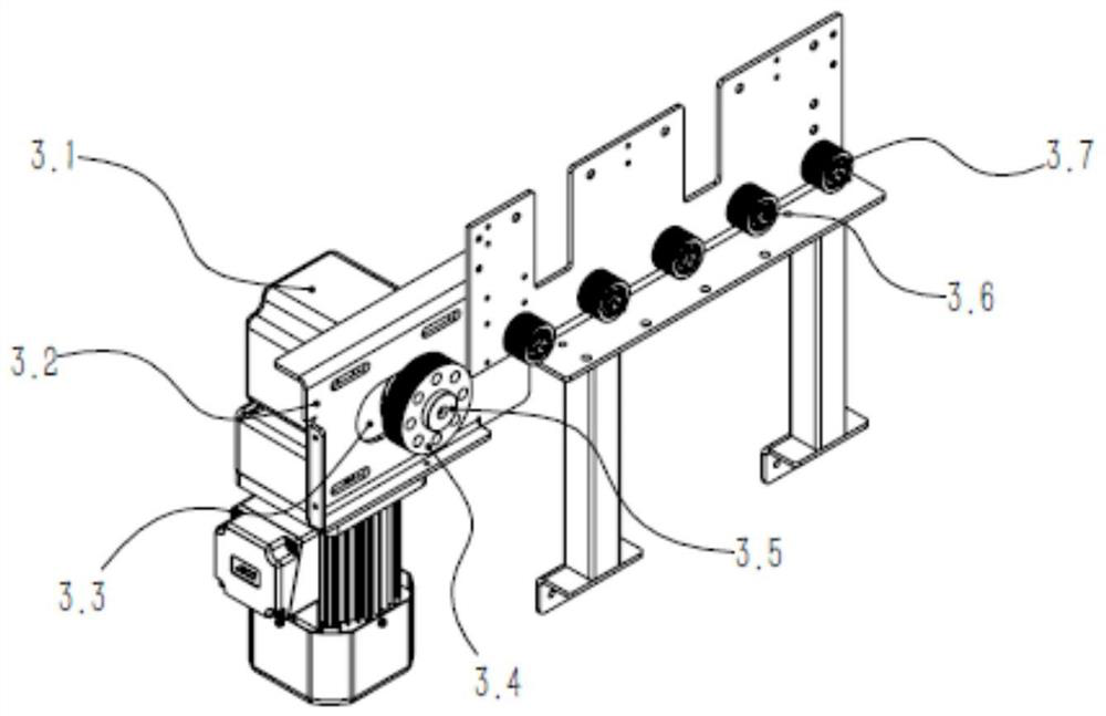
[0030] 1. The direction of the main conveying line adopts the multi-ribbed belt roller transmission method.

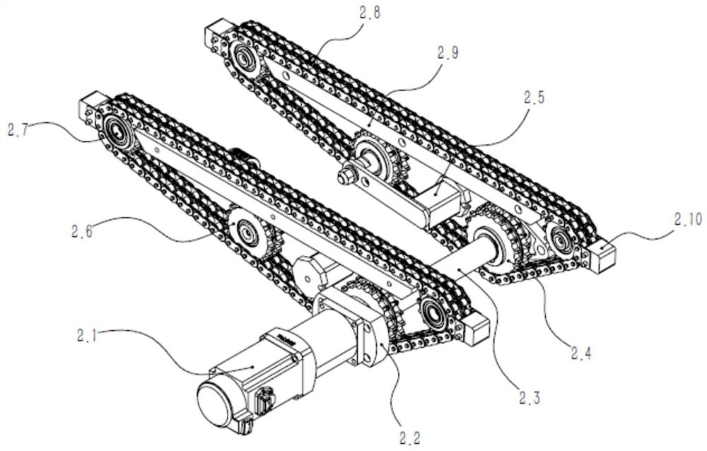
[0031] 2. The lateral transfer adopts the servo motor to drive the transfer chain, which drives the transfer block to transfer the goods or the turnover box to the conveying auxiliary line for transmission.

[0032] 3. The goods or turnover boxes are controlled by photoelectricity to control the rise and fall of the blocking mechanism, so that the goods or turnover boxes are waiting for transfer or release at the transfer place.

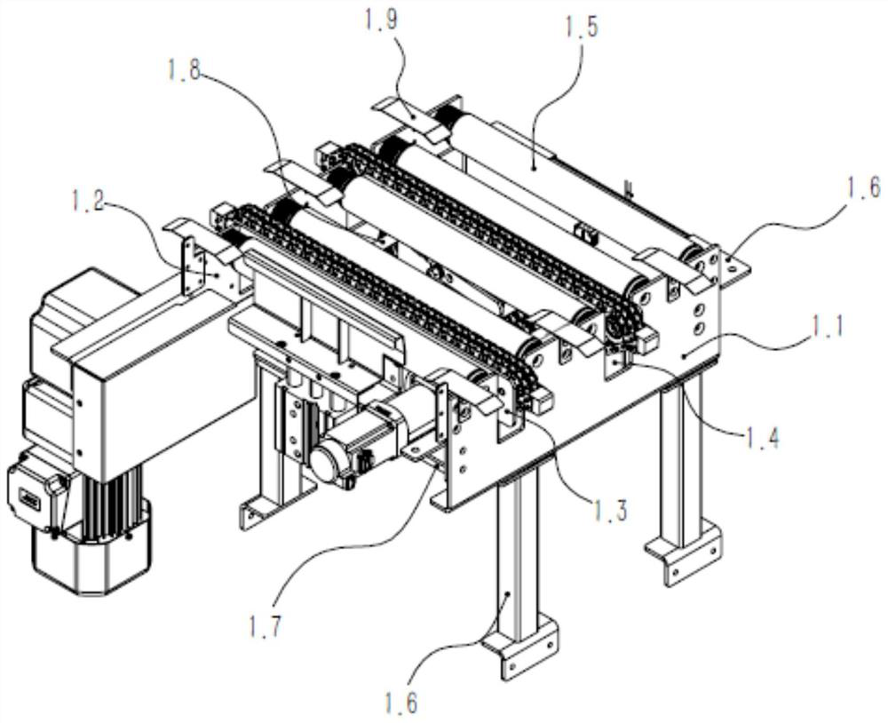
[0033] Lateral transfer mechanism, see figure 1 , including the roller left side plate 1.1, the roller right side plate 1.2, the roller left side plate 1.1 and the roller right side plate 1.2 are respectively mounted on the transfer base plate 1.7. The upper end...


PUM


Abstract

The invention provides a transverse transferring mechanism which comprises a rack, transfer rollers and transfer chains are arranged on the rack, the moving direction of the transfer chains is consistent with the axial direction of the transfer rollers, and transfer shifting blocks are arranged on the transfer chains. A telescopic barrier plate is arranged at the tail end of the transfer stroke on the rack. According to the transverse transferring mechanism, the transferring chains and a blocking mechanism are used in cooperation, a traditional transverse transferring structure with jacking and a belt is replaced, the mechanical structure is greatly simplified, and the manufacturing cost is effectively reduced. A servo motor synchronously drives the two transfer chains to reciprocate through coaxial chain wheels, and bidirectional transfer of goods or turnover boxes is achieved.

Description

technical field [0001] The invention relates to the technical field of logistics conveying equipment, in particular to a lateral transfer mechanism on a logistics conveying assembly line. Background technique [0002] The automated production line generally has a main conveying line and an auxiliary conveying line. The goods or turnover boxes are entered from the main conveying line, and then transferred to the auxiliary conveying line as needed during the transportation process to transport the goods or turnover boxes to the required station. Perform manual operations. In this process, the transfer machine is used to change the conveying direction of the goods or the turnover box, and send the goods or the turnover box into or out of the main conveying line. [0003] At present, the commonly used transfer mechanism is a duplex displacement carrier, which includes a base and a jacking device, and uses two parallel belts to drive the objects to run. However, due to the gap ...

Claims


Application Information

Patent Timeline
IPC IPC(8): B65G47/34B65G47/88B65G43/08B65G13/07B65G23/44B65G23/06B65G23/22B65G21/20
CPCB65G47/34B65G47/8815B65G43/08B65G13/07B65G23/44B65G23/06B65G23/22B65G21/20
Inventor 肖勇民叶众周鑫陈照均
Owner 上海发网云物流科技有限公司
Learn More