Energy storage plate, constant temperature box and working method of constant temperature box
A technology of incubator and plate body, which is applied in the direction of containers, packaging items, special packaging items, etc., can solve the problems of small heat exchange area, easy leakage of cold storage plates, troublesome production of cold storage plates, etc., so as to increase the heat exchange area, Compact and stable structure for improved fit
- Summary
- Abstract
- Description
- Claims
- Application Information
AI Technical Summary
Problems solved by technology
Method used
Image
Examples
Embodiment 1
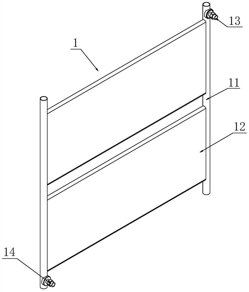
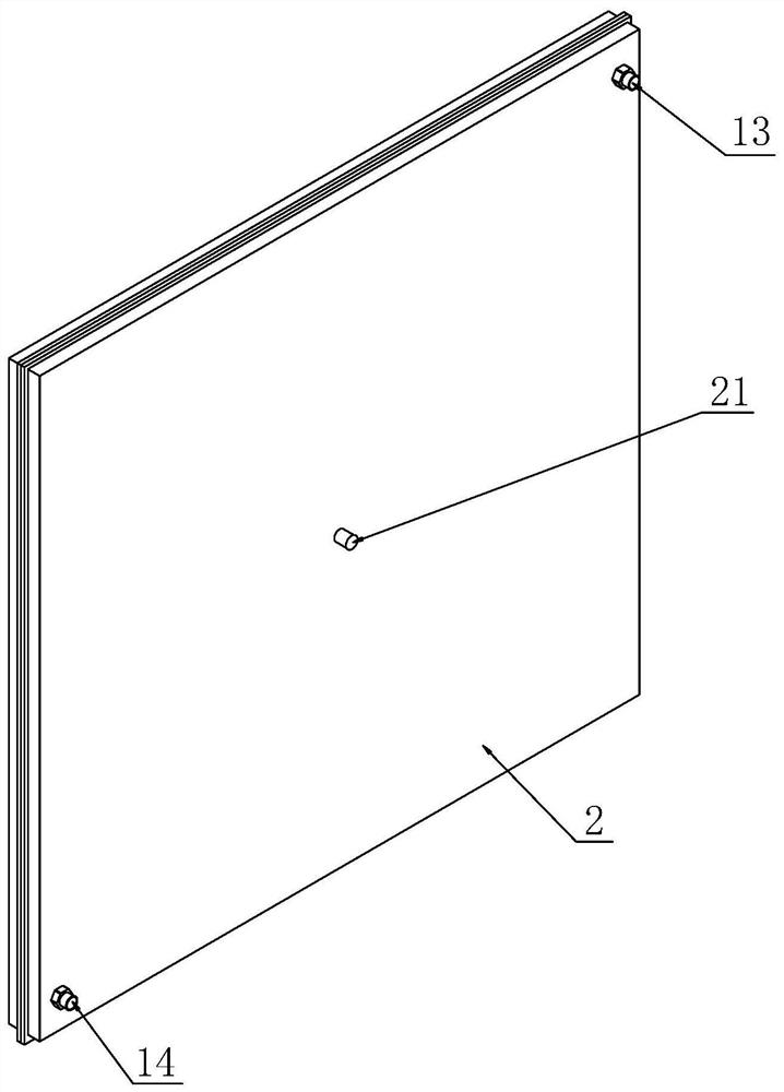
[0027] This embodiment takes cold storage as an example to illustrate the technical solution of the present invention, such as figure 1 , 2 As shown, a cold storage plate includes a hollow plate body 2 and a plate core 1 arranged in the plate body 2. Both the plate body 2 and the plate core 1 are made of aluminum, and the plate core 1 includes two parallel arranged main pipes 11 and a plate core 1. Two flat tubes 12 are arranged in parallel between the two main pipes 11. The two flat tubes 12 and the two main pipes 11 are located in the same plane and communicate with each other to form a single unit of the refrigerant flow channel. The plate core 1 is provided with a load supply The inlet 13 and the outlet 14 for the refrigerant to enter and exit; the outer wall of the plate core 1 and the inner wall of the plate body 2 form a accommodating cavity for accommodating the cooling agent, and the plate body 2 is provided with a filling port 21 for filling the cooling agent. In thi...
Embodiment 2
[0030] This embodiment takes cold storage as an example to illustrate the technical solution of the present invention, such as figure 1 and figure 2As shown, a cold storage plate includes a hollow plate body 2 and a plate core 1 arranged in the plate body 2. The plate core 1 is made of aluminum, the plate body 2 is made of plastic material, and the plate core 1 includes two parallel arranged main pipes 11. And two flat tubes 12 arranged between the two main pipes 11 and arranged in parallel, the two flat pipes 12 and the two main pipes 11 are located in the same plane, and are connected internally to form a single unit of the refrigerant flow channel cavity. The inlet 13 and the outlet 14 for the entry and exit of the carrier refrigerant; the outer wall of the plate core 1 and the inner wall of the plate body 2 form a accommodating cavity for accommodating the refrigerating agent, and the plate body 2 is provided with a filling port 21 for filling the refrigerating agent. In...
Embodiment 3
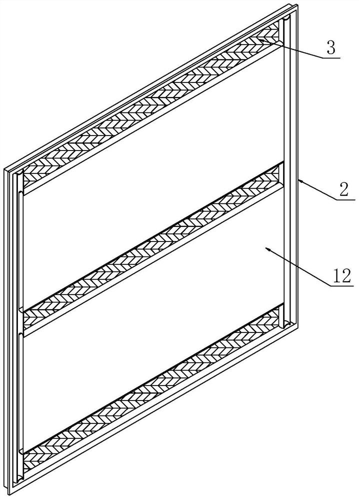
[0033] This embodiment takes cold storage as an example to illustrate the technical solution of the present invention, such as figure 1 , 2 As shown in and 3, a cold storage plate includes a hollow plate body 2 and a plate core 1 arranged in the plate body 2. The plate core 1 is made of aluminum, the plate body 2 is made of plastic material, and the plate core 1 includes two parallel arranged The main pipe 11 and the two flat pipes 12 arranged between the two main pipes 11 and arranged in parallel, the two flat pipes 12 and the two main pipes 11 are located in the same plane and communicate with each other to form a single coolant flow channel cavity. There is an inlet 13 and an outlet 14 for the cooling medium to enter and exit; the outer wall of the plate core 1 and the inner wall of the plate body 2 form a accommodating cavity for accommodating the cooling storage agent, and the plate body 2 is provided with a filling port 21 for filling the cooling storage agent. In this ...
PUM
 Abstract
Description
Claims
Application Information
 - R&D Engineer
- R&D Manager
- IP Professional
- Industry Leading Data Capabilities
- Powerful AI technology
- Patent DNA Extraction
Browse by: Latest US Patents, China's latest patents, Technical Efficacy Thesaurus, Application Domain, Technology Topic, Popular Technical Reports.
© 2024 PatSnap. All rights reserved.Legal|Privacy policy|Modern Slavery Act Transparency Statement|Sitemap|About US| Contact US: help@patsnap.com


