Oil seal transition sleeve and opening expanding tool for machining oil seal transition sleeve

A transition sleeve and oil seal technology, applied in the field of transition sleeves, can solve the problems of easy scrapping, difficult machining, inconvenient processing and management of oil seal transition sleeves, etc., and achieve the effect of improving product quality, not easy to scrap, and easy to process

Active Publication Date: 2021-09-24
浙江亚之星汽车部件有限公司
View PDF7 Cites 0 Cited by
  • Summary
  • Abstract
  • Description
  • Claims
  • Application Information

AI Technical Summary

Problems solved by technology

[0003] The traditional oil seal transition sleeve is formed by machining with a metal round rod or a non-metallic round rod according to the needs. One end of the processed traditional oil seal transition sleeve is similar to the shape of a bullet, and the other end is tubular and wraps the part when used. The tube wall It is very thin and has a deep tube hole. The unique structure of the traditional oil seal transition sleeve makes machining difficult and easy to scrap. In addition, in the shock absorber industry, there are a large number of shock absorber products, and almost every shock absorber product requires a dedicated Oil seal transition sleeve, which brings great inconvenience to the processing and management of oil seal transition sleeve

Method used


Image

  • Oil seal transition sleeve and opening expanding tool for machining oil seal transition sleeve
  • Oil seal transition sleeve and opening expanding tool for machining oil seal transition sleeve
  • Oil seal transition sleeve and opening expanding tool for machining oil seal transition sleeve

Examples


Embodiment Construction

[0028] Below will combine in the embodiment of the present invention Figure 1 to Figure 6 , clearly and completely describe the technical solutions in the embodiments of the present invention, obviously, the described embodiments are only some of the embodiments of the present invention, not all of them. Based on the embodiments of the present invention, all other embodiments obtained by persons of ordinary skill in the art without creative efforts fall within the protection scope of the present invention.

[0029] In order to make the objectives, technical solutions and advantages of the present invention clearer, the technical solutions in the embodiments of the present invention will be described in more detail below in conjunction with the drawings in the embodiments of the present invention.

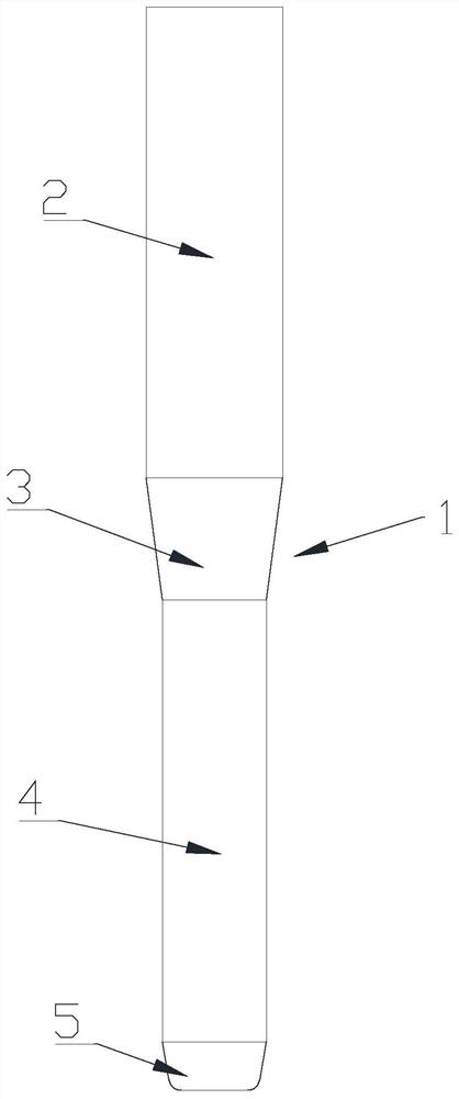
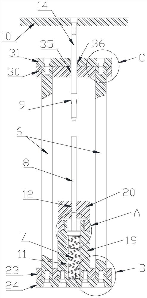
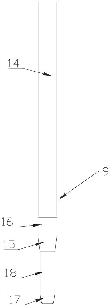
[0030] Such as Figure 1 to Figure 6As shown, an oil seal transition sleeve 1 disclosed in this embodiment, the oil seal transition sleeve 1 is a thin-walled hollow structure, the...


PUM


Abstract

The invention relates to the field of transition sleeves, in particular to an oil seal transition sleeve which is of a thin-wall hollow structure. The oil seal transition sleeve comprises a connecting pipe, a transition pipe and a guide pipe, the connecting pipe is arranged at one end of the transition pipe, the guide pipe is arranged at the other end of the transition pipe, the diameter of the connecting pipe is larger than that of the guide pipe, and the transition pipe is in a circular truncated cone shape. The invention further relates to an opening expanding tool for machining the oil seal transition sleeve, the opening expanding tool for machining the oil seal transition sleeve comprises a lower die lower base, a lower die upper base, a supporting column, a positioning base, a spring, a positioning rod, the opening expanding die and an upper die bottom plate moving up and down, structural design is reasonable, and the connecting pipe and the transition pipe can be conveniently formed through opening expanding machining. According to the oil seal transition sleeve and the opening expanding tool for machining the oil seal transition sleeve, the oil seal transition sleeve is reasonable in structural design and convenient to machine and manufacture, the opening expanding tool is reasonable in structural design, the oil seal transition sleeve meeting actual requirements can be efficiently machined, oil seal transition sleeves of different specifications can be conveniently machined after the tool is replaced. In this way, actual machining requirement can be better met.

Description

technical field [0001] The invention relates to the technical field of transition sleeves, in particular to an oil seal transition sleeve and an expansion tool for processing thereof. Background technique [0002] When assembling the oil seal of the electronically controlled shock absorber solenoid valve, an oil seal transition sleeve is required, which can ensure the integrity of the oil seal to the greatest extent and improve the sealing effect. [0003] The traditional oil seal transition sleeve is formed by machining with a metal round rod or a non-metallic round rod according to the needs. One end of the processed traditional oil seal transition sleeve is similar to the shape of a bullet, and the other end is tubular and wraps the part when used. The tube wall It is very thin and has a deep tube hole. The unique structure of the traditional oil seal transition sleeve makes machining difficult and easy to scrap. In addition, in the shock absorber industry, there are a la...

Claims


Application Information

Patent Timeline
Patent Type & Authority Applications(China)
IPC IPC(8): B21D31/04F16J15/00
CPCB21D31/04F16J15/00
Inventor 林圣浦周崇宝高新原
Owner 浙江亚之星汽车部件有限公司
Why Eureka
Try Eureka