Pulse electroplating method for solving color difference of appearance of thin plate

A pulse electroplating, thin plate technology, applied in jewelry and other directions, can solve the problem of thin plate appearance color difference, and achieve the effect of reducing wrinkles and uniform appearance color

Pending Publication Date: 2021-09-24
江西景旺精密电路有限公司
View PDF4 Cites 0 Cited by
  • Summary
  • Abstract
  • Description
  • Claims
  • Application Information

AI Technical Summary

Problems solved by technology

[0004] The problem to be solved by the present invention is to provide a pulse electroplating method to solve the appearance color difference of the thin plate. By setting different waveform

Method used


Image

  • Pulse electroplating method for solving color difference of appearance of thin plate
  • Pulse electroplating method for solving color difference of appearance of thin plate
  • Pulse electroplating method for solving color difference of appearance of thin plate

Examples


Embodiment 1

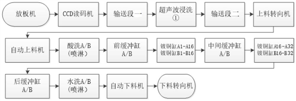
[0024] A pulse electroplating method for solving thin plate appearance color difference, said method comprises the following steps,

[0025] (1) The thin plate is placed in the conveying section through the plate placing machine, and then transported to the ultrasonic immersion section for immersion;

[0026] (2) After the dipping is completed, it is transported to the feeding steering machine through the second conveying section, and after the thin plate is turned, it is transported to the pickling section through the automatic feeding machine for pickling;

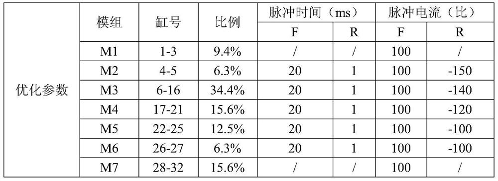
[0027] (3) After pickling, it is transported to the copper plating cylinder. The copper plating cylinder is divided into 7 sections. The waveform parameters are set separately for each section. The reverse current intensity in the waveform parameters is from strong to weak. Among them, the copper plating cylinder of the first section is not Apply reverse current, the positive and negative current ratio of the second copp...

Embodiment 2

[0037] A pulse electroplating method for solving thin plate appearance color difference, said method comprises the following steps,

[0038] (1) The thin plate is placed in the conveying section through the plate placing machine, and then transported to the ultrasonic immersion section for immersion;

[0039] (2) After the dipping is completed, it is transported to the feeding steering machine through the second conveying section, and after the thin plate is turned, it is transported to the pickling section through the automatic feeding machine for pickling;

[0040] (3) After pickling, it is transported to the copper plating cylinder. The copper plating cylinder is divided into 7 sections. The waveform parameters are set separately for each section. The reverse current intensity in the waveform parameters is from strong to weak. Among them, the copper plating cylinder of the first section is not Apply reverse current, the positive and negative current ratio of the second copp...

Embodiment 3

[0048] A pulse electroplating method for solving thin plate appearance color difference, said method comprises the following steps,

[0049] (1) The thin plate is placed in the conveying section through the plate placing machine, and then transported to the ultrasonic immersion section for immersion;

[0050] (2) After the dipping is completed, it is transported to the feeding steering machine through the second conveying section, and after the thin plate is turned, it is transported to the pickling section through the automatic feeding machine for pickling;

[0051] (3) After pickling, it is transported to the copper plating cylinder. The copper plating cylinder is divided into 7 sections. The waveform parameters are set separately for each section. The reverse current intensity in the waveform parameters is from strong to weak. Among them, the copper plating cylinder of the first section is not Apply reverse current, the positive and negative current ratio of the second copp...


PUM


Abstract

The invention discloses a pulse electroplating method for solving the color difference of the appearance of a thin plate. The method is characterized by comprising the following steps: (1) placing the thin plate on a conveying section I through a plate placing machine, and conveying the thin plate to an ultrasonic immersion cleaning section for immersion cleaning; (2) after immersion cleaning is completed, the thin plate is conveyed to a feeding steering machine through a second conveying section, and after steering, the thin plate is conveyed to an acid pickling section through an automatic feeding machine for acid pickling; (3) after acid pickling, the copper is conveyed to a copper plating cylinder, the copper plating cylinder is divided into seven sections, waveform parameters are set for the sections separately, and the reverse current intensities in the waveform parameters are decreased from high to low; and (4) after copper plating is completed, the thin plate is conveyed to an automatic discharging machine for discharging. According to the pulse electroplating method, the phenomenon of color difference of appearance is solved by setting different waveform parameters, and the problems of wrinkling and bubbling of the dry film of the outer circuit caused by the phenomenon can be effectively reduced.

Description

technical field [0001] The invention relates to the technical field of PCB board manufacturing methods, in particular to a pulse electroplating method for solving the color difference in the appearance of thin boards. Background technique [0002] PCB (Printed Circuit Board), the Chinese name is printed circuit board, also known as printed circuit board, printed circuit board, is an important electronic component, a support for electronic components, and a provider of electrical connections for electronic components. Because it is made using electronic printing, it is called a "printed" circuit board. [0003] The reverse waveform in the production parameters of the pulse electroplating VCP line in the industry is usually set according to the plate thickness or aspect ratio: for example, for a plate with an aspect ratio of 8:1, the positive and negative current intensity ratio is (100%: -180%), The time ratio of positive and negative plating is (20ms: 1ms). For boards produ...

Claims


Application Information

Patent Timeline
IPC IPC(8): C25D5/18C25D7/00
CPCC25D5/18C25D7/00
Inventor 舒浩王正坤张伦亮周锋朱爱军张广志
Owner 江西景旺精密电路有限公司
Why Eureka
Try Eureka