External oil filling type shield hob

An oil-filled hob technology, applied in mining equipment, earthwork drilling, tunnels, etc., can solve problems such as seal failure, hob failure, and damaged bearings, so as to prevent hob failure, reduce damage, and improve service life Effect

Pending Publication Date: 2021-09-24
广州市力劲机电有限公司 +1
View PDF15 Cites 2 Cited by
  • Summary
  • Abstract
  • Description
  • Claims
  • Application Information

AI Technical Summary

Problems solved by technology

[0005] The purpose of the present invention is to address the above-mentioned deficiencies and provide an external oil-filled shield hob to solve the problem that the shield machine in the prior art is prone to seal failure during the excavation process of the complex stratum, and the lubricating oil chamber enters the mud and sand to damage the bearing. , the problem that causes the hob to fail

Method used


Image

  • External oil filling type shield hob
  • External oil filling type shield hob
  • External oil filling type shield hob

Examples


Embodiment 1

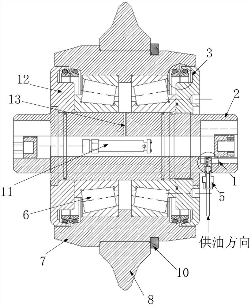
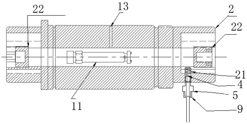
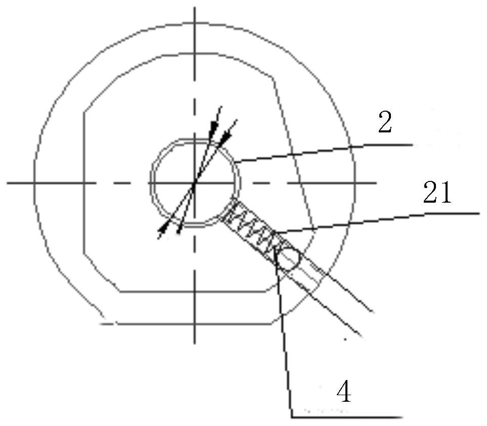
[0030] Such as Figure 1 to Figure 4 As shown, Embodiment 1 of the present invention provides an external oil-filled shield hob, the external oil-filled shield hob is an external oil-filled single-blade hob, specifically a 17-inch external oil-filled single-blade hob The knife is suitable for shield tunneling construction, especially for tunneling construction in composite ground. The outer oil-filled single-edged hob comprises: a cutter hub 7, two bearings 6 are arranged inside the cutter hub 7, a hollow cutter shaft 2 is arranged inside the bearing 6, end caps 12 are arranged at both ends of the cutter hub 7, and the hollow cutter shaft The two ends of 2 pass through the end cover 12, and the outside of the cutter hub 7 is provided with a cutter ring 8.

[0031] Specifically, the inner ring of the bearing 6 is mounted on the hollow cutter shaft 2 with an interference fit, the outer ring of the bearing 6 is installed in the cutter hub 7 through an interference fit, and the c...

Embodiment 2

[0039] see Figure 5 to Figure 7 , Embodiment 2 of the present invention also provides an external oil-filled shield hob, the external oil-filled shield hob is an external oil-filled central double hob, specifically a 17-inch external oil-filled central double The hob, the outer oil-filled center duplex hob includes: two cutter hubs 7, the two cutter hubs 7 are arranged side by side, each cutter hub 7 is provided with two bearings 6, and the bearings 6 are provided with a hollow cutter shaft 2 , the outer end of the cutter hub 7 is provided with an end cover 12, and an intermediate block 14 is arranged between the two cutter hubs 7; the two ends of the hollow cutter shaft 2 extend to the outer end surface of the end cover 12, and each cutter hub 7 is set There are 8 knife rings.

[0040] Specifically, the inner ring of the bearing 6 is mounted on the hollow cutter shaft 2 with an interference fit, the outer ring of the bearing 6 is installed in the cutter hub 7 through an int...


PUM


Abstract

The invention discloses an external oil filling type shield hob. The external oil filling type shield hob comprises a hob hub, two bearings are arranged in the hob hub, a hollow hob shaft is arranged in the bearings, end covers are arranged at the two ends of the hob hub, the two ends of the hollow hob shaft penetrate through the end covers, and a hob ring is arranged outside the hob hub; a grease supplementing through hole communicated with the interior of the hollow hob shaft is formed at one end of the hollow hob shaft, and the grease supplementing through hole is provided with a supplementary lubrication system; the supplementary lubrication system comprises a first one-way valve arranged in the grease supplement through hole, an oil pipe joint and an oil pipe; the hollow hob shaft is provided with a lubricating oil cavity communicating hole communicating with the area between the two bearings, a wireless temperature and pressure sensor is arranged in the hollow hob shaft, and shaft end oil plugs are arranged at the two ends of the hollow hob shaft. a floating sealing system is arranged between the end covers and the hob hub; and the problems that a shield tunneling machine is prone to sealing failure in the composite stratum tunneling process, mud and sand enter a lubricating oil cavity to damage a bearing, and consequently a hob loses efficacy are solved.

Description

technical field [0001] The invention relates to the technical field of shield tunneling, in particular to an external oil-filled shield hob. Background technique [0002] At present, the shield method has become one of the main construction methods of tunnel engineering. The shield method cuts the rock and soil through the cutter head of the shield machine. The cutter head is equipped with cutters, scrapers, hobs, and advanced knives. knives. The hob is mainly composed of cutter ring, cutter hub, cutter shaft, bearing, floating seal, end cover and other components. The floating seal is a key component to ensure the internal pressure of the hob and the normal operation of the bearing. Once the floating seal system fails, there will be problems with the bearing system, which will cause the entire hob to fail and be scrapped in a very short time. Therefore, it is necessary to ensure that there is enough grease on the working friction surface of the floating sealing system an...

Claims


Application Information

Patent Timeline
Patent Type & Authority Applications(China)
IPC IPC(8): E21D9/08E21D9/093
CPCE21D9/08E21D9/0635E21D9/093
Inventor 关维军杨泊张殿韶孙健教富超刘兴国林健民黄明
Owner 广州市力劲机电有限公司
Why Eureka
Try Eureka