
Optical system, lens module and electronic device

An optical system and lens technology, applied in optics, optical components, instruments, etc., can solve problems such as unfavorable miniaturization design, large field of view and small range, and inability to obtain object space information

Active Publication Date: 2021-09-24
JIANGXI JINGCHAO OPTICAL CO LTD
View PDF6 Cites 8 Cited by
  • Summary
  • Abstract
  • Description
  • Claims
  • Application Information

AI Technical Summary

Problems solved by technology

[0003] Most of the vehicle-mounted camera lenses currently on the market are difficult to meet the requirements of large field of view and miniaturization at the same time. When the camera lens meets the requirements of miniaturization, the range of large field of view is small, and it is impossible to obtain sufficient object space information; Expanding the field of view range of the camera lens is not conducive to miniaturization design

Method used


Image

  • Optical system, lens module and electronic device
  • Optical system, lens module and electronic device
  • Optical system, lens module and electronic device

Examples


no. 1 example

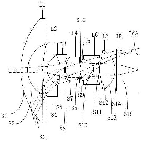
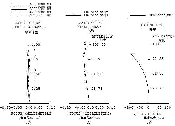
[0043] Please refer to figure 1 and figure 2 , the optical system of this embodiment includes in sequence from the object side to the image side along the optical axis direction:

[0044] The first lens L1 has a negative refractive power. The object side S1 of the first lens L1 is convex at the near optical axis, and the image side S2 of the first lens L1 is concave at the near optical axis.

[0045] The second lens L2 has a negative refractive power. The object side S3 of the second lens L2 is convex at the near optical axis, and the image side S4 of the second lens L2 is concave at the near optical axis.

[0046] The third lens L3 has negative refractive power, and both the object side S5 and the image side S6 of the third lens L3 are concave at the near optical axis.

[0047] The fourth lens L4 has positive refractive power. The object side S7 of the fourth lens L4 is convex at the near optical axis, and the image side S8 of the fourth lens L4 is concave at the near opti...

no. 2 example

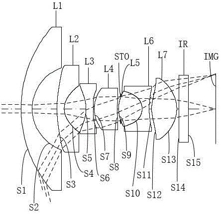
[0067] Please refer to image 3 and Figure 4 , the optical system of this embodiment includes in sequence from the object side to the image side along the optical axis direction:

[0068] The first lens L1 has a negative refractive power. The object side S1 of the first lens L1 is convex at the near optical axis, and the image side S2 of the first lens L1 is concave at the near optical axis.

[0069] The second lens L2 has a negative refractive power. The object side S3 of the second lens L2 is convex at the near optical axis, and the image side S4 of the second lens L2 is concave at the near optical axis.

[0070] The third lens L3 has negative refractive power, and both the object side S5 and the image side S6 of the third lens L3 are concave at the near optical axis.

[0071] The fourth lens L4 has positive refractive power. The object side S7 of the fourth lens L4 is convex at the near optical axis, and the image side S8 of the fourth lens L4 is concave at the near opti...

no. 3 example

[0084] Please refer to Figure 5 and Figure 6 , the optical system of this embodiment includes in sequence from the object side to the image side along the optical axis direction:

[0085] The first lens L1 has a negative refractive power. The object side S1 of the first lens L1 is convex at the near optical axis, and the image side S2 of the first lens L1 is concave at the near optical axis.

[0086] The second lens L2 has a negative refractive power. The object side S3 of the second lens L2 is convex at the near optical axis, and the image side S4 of the second lens L2 is concave at the near optical axis.

[0087] The third lens L3 has negative refractive power, and both the object side S5 and the image side S6 of the third lens L3 are concave at the near optical axis.

[0088] The fourth lens L4 has positive refractive power. The object side S7 of the fourth lens L4 is convex at the near optical axis, and the image side S8 of the fourth lens L4 is concave at the near opt...


PUM


Abstract

The invention discloses an optical system, a lens module and an electronic device. The optical system sequentially comprises from an object side to an image side along an optical axis: a first lens to a seventh lens, in which the first, second, third and sixth lenses each have negative refractive power, the fourth, fifth and seventh lenses each have positive refractive power, the mirror surface of the third lens is a concave surface in a paraxial region, the mirror surfaces of the fifth lens and the seventh lens are convex in a paraxial region. The optical system satisfies the following relational expressions: 10.5<TTL / f<12, wherein TTL is the distance from the object side surface of the first lens to the imaging surface on the optical axis, and f is the effective focal length of the optical system. By reasonably designing the surface types and the refractive power of the first to seventh lenses and limiting the relationship between the total length of the optical system and the focal length of the optical system through the relational expression, the total length of the optical system is controlled while the field angle range of the optical system is met, so that the miniaturization characteristic of the optical system is met.

Description

technical field [0001] The invention belongs to the technical field of optical imaging, and in particular relates to an optical system, a lens module and electronic equipment. Background technique [0002] With the development of the automotive industry, the technical requirements for automotive driving assistance cameras such as front view, side view, automatic cruise, driving recorder, and reversing images are getting higher and higher. The side-view camera allows the driver to intuitively identify and monitor obstacles and pedestrians in the blind spots on the left and right sides of the car while the car is driving, so that the car can turn when passing through special places (such as intersections, roadblocks, parking lots, etc.). When turning around, the side-view camera can be turned on at any time to make judgments on the driving environment and feed back to the car central system to make correct instructions to avoid driving accidents. Provide a basis for the judgm...

Claims


Application Information

Patent Timeline
Patent Type & Authority Applications(China)
IPC IPC(8): G02B13/00G02B13/06G02B13/18G03B30/00
CPCG02B13/0045G02B13/06G02B13/18G02B13/006G03B30/00
Inventor 乐宇明兰宾利赵迪其他发明人请求不公开姓名
Owner JIANGXI JINGCHAO OPTICAL CO LTD
Learn More