Heat transfer characteristic analysis method for heat pipe in nuclear power system

An analysis method and technology of heat transfer characteristics, applied in the field of heat transfer characteristics analysis of heat pipes in offshore nuclear power systems, can solve problems such as leakage of radioactive coolant, insufficient passiveness, and danger

Active Publication Date: 2021-09-24
XI AN JIAOTONG UNIV
View PDF7 Cites 8 Cited by
  • Summary
  • Abstract
  • Description
  • Claims
  • Application Information

AI Technical Summary

Problems solved by technology

The C-type heat exchanger in the passive waste heat removal system of a typical nuclear reactor AP1000, the principle is that the reactor coolant flows through the tube, and the cooling water flows through the shell side to exchange heat. This type of heat exchanger is used in reactors in harsh offshore environments. There are potential safety hazards: (1) Fluid circulation requires power, and its passiveness is insufficient; (2) The coolant in the main circuit is radiated by nuclear fuel. If the heat exchange pipes or connecting pipes and baffles are damaged, the radioactive coolant will leak and produce Dangerous; (3) When the nuclear reactor is shut down or in accident conditions, the passive waste heat removal system is put into operation, and the coolant suddenly flows into the heat exchanger tube to exchange heat with the cold water outside the tube, which is prone to water hammer and vibration damage to the heat exchanger; (4 ) If one tube fails, the entire heat exchanger will not function properly

Method used


Image

  • Heat transfer characteristic analysis method for heat pipe in nuclear power system
  • Heat transfer characteristic analysis method for heat pipe in nuclear power system
  • Heat transfer characteristic analysis method for heat pipe in nuclear power system

Examples


Embodiment Construction

[0130] The present invention will be further described in detail below with reference to the accompanying drawings and specific embodiments.

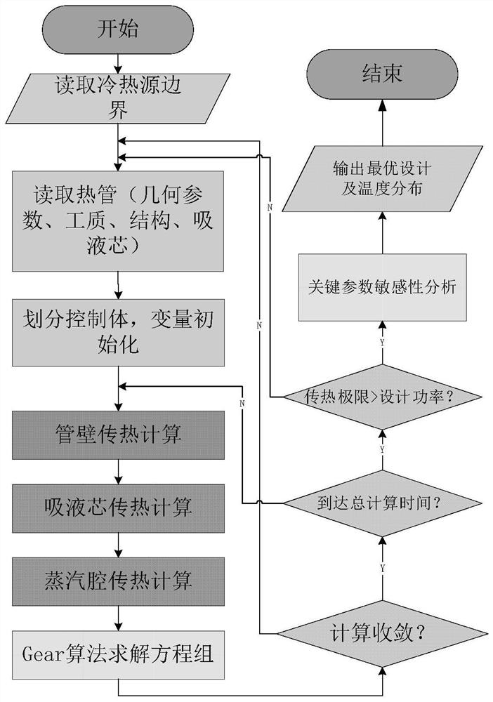
[0131] like figure 1 Shown, the heat transfer characteristic analysis method of heat pipe in a kind of nuclear power system of the present invention, the steps are as follows:

[0132] Step 1: Input the heat source and heat sink conditions of the heat pipe, the heat source is the electric heating wire heating with a given heat flux density or the flow heating with a given surface heat transfer coefficient and hot fluid temperature; the heat sink is a given surface heat transfer coefficient and cold fluid temperature Sweep cooling or casing cooling; input the working fluid, structure and geometric parameters of the heat pipe, and set the total calculation time;

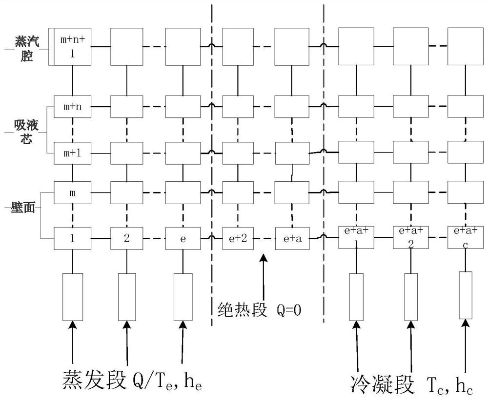
[0133] Step 2: If figure 2 As shown, the heat pipe wall and liquid-absorbing core are divided into m layers and n layers along the thickness direction, and the steam chamber...


PUM


Abstract

A heat transfer characteristic analysis method for a heat pipe in a nuclear power system mainly comprises the following steps that 1, inputting a heat source of the heat pipe, the working condition of a heat trap, a working medium, a structure and geometric parameters, and setting calculation time; 2, dividing the heat pipe into control bodies and carrying out initialized calculation; 3, calculating the change rate of the temperature of the pipe wall control body along with time, and considering the axial heat transfer and boundary conditions of the heat pipe; 4, calculating the change rate of the temperature of the control body in the wick along with time, ignoring convective heat transfer caused by liquid flow, and regarding the change rate as pure heat conduction; 5, calculating the change rate of the temperature of the control body in the steam cavity along with time, and simplifying continuous steam flowing into thermal resistance heat conduction; 6, solving the equation set by using a Gear algorithm, and completing calculation of all time points; 7, checking the heat transfer limit of the heat pipe and calculating equivalent thermal resistance; 8, comparing and analyzing the influence of the heat pipe key parameters on the heat transfer performance. Transient calculation and heat transfer characteristic analysis are carried out on different heat pipes, and suggestions and guidance are provided for design of a high-performance heat pipe heat exchanger in a nuclear power system.

Description

technical field [0001] The invention relates to a heat exchange technology in the field of nuclear power technology, in particular to a method for analyzing heat transfer characteristics of a heat pipe in an offshore nuclear power system. Background technique [0002] After the Fukushima nuclear accident, the passive safety device for removing the waste heat from the core of the nuclear reactor has been widely studied by scholars. Compared with the land nuclear power, the waste heat removal system of offshore nuclear power is relatively backward, and the working environment is harsh and the safety requirements are higher. The working marine environment is the most ideal and convenient heat sink for waste heat discharge, which is a natural advantage. The C-type heat exchanger in the passive waste heat removal system in a typical nuclear reactor AP1000, the principle is that the reactor coolant flows through the tube, and the cooling water flows through the shell side for heat...

Claims


Application Information

Patent Timeline
Patent Type & Authority Applications(China)
IPC IPC(8): G06F30/18G06F30/28G06F113/08G06F113/14G06F119/08G06F119/14
CPCG06F30/18G06F30/28G06F2113/08G06F2113/14G06F2119/08G06F2119/14Y02E30/30
Inventor 王成龙段倩妮田智星苏光辉秋穗正田文喜张大林
Owner XI AN JIAOTONG UNIV
Why Eureka
Try Eureka