
Cutting blade and cutting tool

A technology for cutting blades and cutting edges, which is applied in the direction of milling cutters, manufacturing tools, metal processing equipment, etc., to improve the surface quality of workpiece processing and the life of cutting blades, improve the effect, and reduce the flow pressure loss

Pending Publication Date: 2021-09-28
KYOCERA CORP
View PDF1 Cites 0 Cited by
  • Summary
  • Abstract
  • Description
  • Claims
  • Application Information

AI Technical Summary

Problems solved by technology

However, there are still some deficiencies in the existing

Method used


Image

  • Cutting blade and cutting tool
  • Cutting blade and cutting tool
  • Cutting blade and cutting tool

Examples


Embodiment Construction

[0030] Typical embodiments that embody the features and advantages of the present invention will be described in detail in the following description. It should be understood that the present invention is capable of various changes in different embodiments without departing from the scope of the present invention, and that the description and illustrations therein are illustrative in nature and not limiting. this invention.

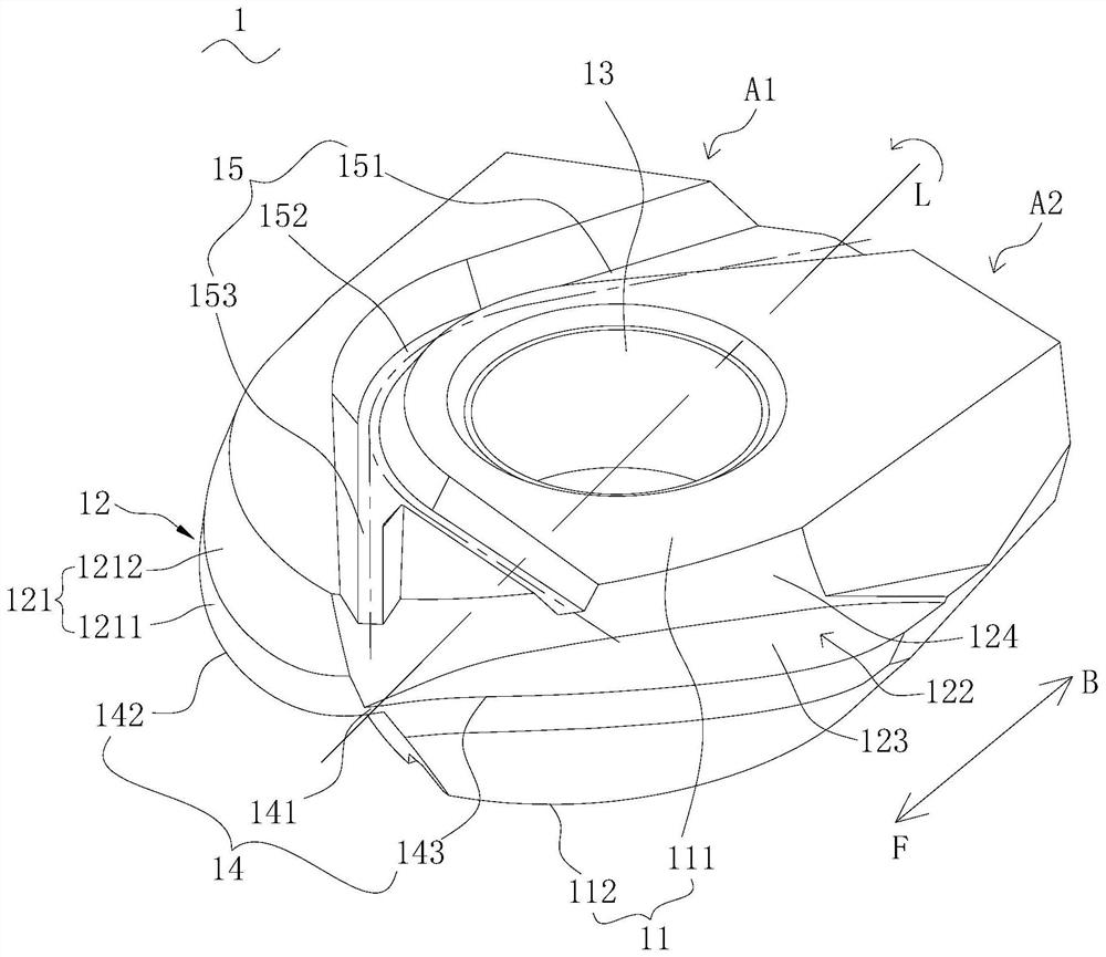
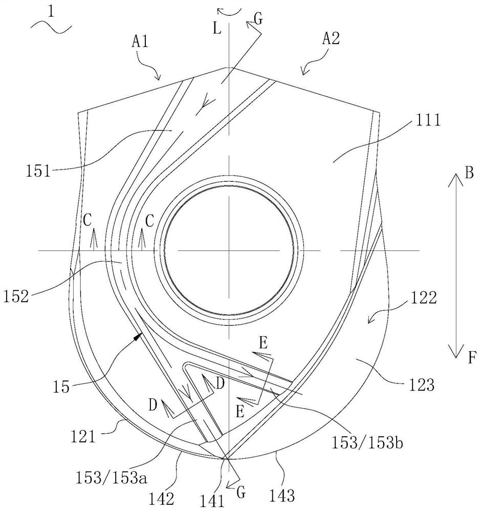
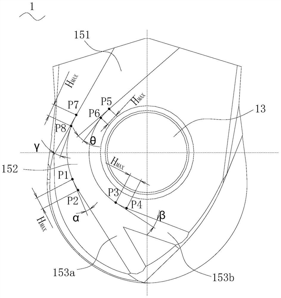
[0031] refer to figure 1 and figure 2 , One embodiment of the present invention provides a cutting insert 1 extending from a rear end B to a front end F along a rotation center axis L. As shown in FIG. The cutting insert 1 has a first area A1 and a second area A2 divided by the rotation center axis L as a boundary.

[0032] The cutting insert 1 has two opposing constraining surfaces 11, an outer peripheral portion 12 located between the two constraining surfaces 11, a through hole 13 formed between the two constraining surfaces 11, and a cutting edge 1...


PUM


Abstract

The invention provides a cutting blade and a cutting tool. The cutting blade extends from the rear end to the front end along the rotation center axis and is provided with a first area and a second area which are divided by taking the rotation center axis as a boundary. The cutting blade comprises a first restraining surface, a second restraining surface, a peripheral part, a through hole and a cutting edge; the cutting edge has a tip cutting edge intersecting with the rotational center axis and a first cutting edge located in a first region of the outer peripheral portion; the first restraining surface is provided with a cooling groove extending from the rear end side to the front end side; the cooling groove comprises an inlet section, a transition section and a plurality of spraying sections; and from the front view of the first restraining surface, the plurality of spraying sections are smoothly connected with the transition section and are provided with first spraying sections extending towards the front end cutting edge. The flow pressure loss of the coolant sprayed towards the front end cutting edge can be reduced, and the coolant cooling effect is improved, so that the service life of the blade is prolonged, and the workpiece machining surface quality is improved.

Description

technical field [0001] The invention relates to the technical field of cutting tools, in particular to a cutting blade and a cutting tool. Background technique [0002] In the cutting of metal materials, end mills are often used for profiling, surface processing, etc. End mills are often processed in a semi-closed environment, and there are problems such as difficulty in discharging iron filings and chipping of cutting edges. These factors will reduce the tool life and affect the surface quality of the workpiece, and setting the cooling system can solve the above problems to varying degrees. But there are still certain deficiencies in the existing ones. [0003] Chinese invention patent CN101695770A discloses a blade finish milling cutter with an internal cooling system, which is provided with a through hole along the central axis of the handle, and a cooling groove and a spray port are provided on the blade. The through hole of the shank communicates with the cooling gro...

Claims


Application Information

Patent Timeline
Patent Type & Authority Applications(China)
IPC IPC(8): B23C5/10B23C5/28
CPCB23C5/109B23C5/1027B23C5/28B23C5/10
Inventor 刘东亨
Owner KYOCERA CORP
Learn More