An intelligent production equipment for pure wooden packaging boxes
A technology for intelligent production and packing boxes, which is applied in the direction of metal processing equipment, grinding/polishing equipment, grinding drive devices, etc., can solve the problems of low degree of automation and intelligence, reduce the production efficiency of pure wooden packing boxes, etc., and achieve improvement Cutting efficiency, high degree of automation, and guaranteed stability
- Summary
- Abstract
- Description
- Claims
- Application Information
AI Technical Summary
Problems solved by technology
Method used
Image
Examples
Embodiment 1
[0034] According to an embodiment of the present invention,
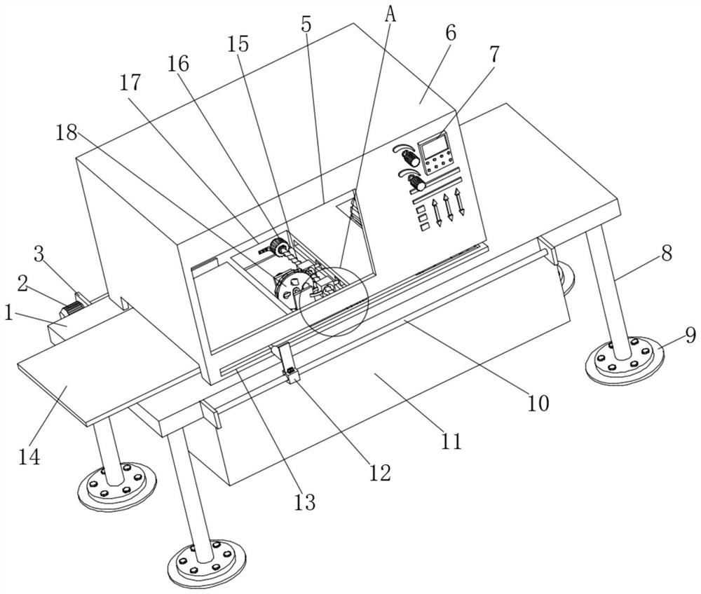
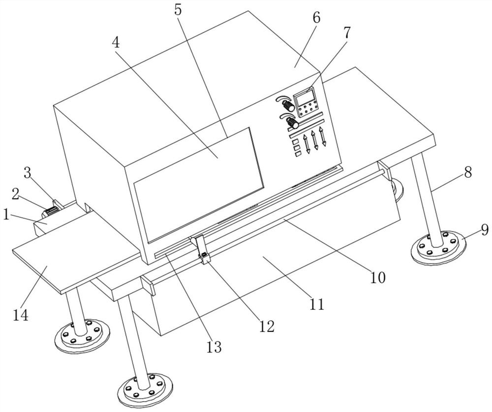
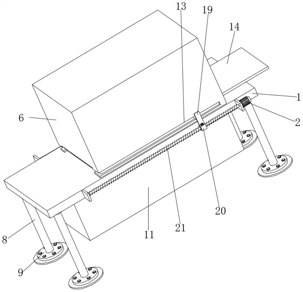
[0035] see Figure 1-7 , an intelligent production equipment for pure wooden packing boxes, comprising a table body 1, a support column 8 is fixedly connected to the bottom of the table body 1, a base 9 is fixedly connected to the bottom of the support column 8, and a dust cover is fixedly connected to the top of the table body 1 6. One side of the dust cover 6 is provided with a feed slot, and a plate body 14 is inserted inside the feed slot. Groove 5, the inside of first through groove 5 is fixedly connected with transparent plate 4, and one side of dustproof cover 6 is fixedly connected with control panel 7, and the top of table body 1 is provided with first installation groove 17, and the first installation groove 17 A cutting wheel 18 is arranged inside, and a first adjustment assembly for driving the cutting wheel 18 to move in the Z-axis direction is arranged inside the first installation groove 17, and a cl...
Embodiment 2
[0037] see figure 1 , 4 , 5. The first adjustment assembly includes a second motor 16 fixedly connected to the inner wall of one side of the first installation groove 17, one end of the output shaft of the second motor 16 is fixedly connected with the first threaded screw 15, and one side of the second motor 16 Fixedly connected with a reinforcing frame, one side of the reinforcing frame is fixedly connected on the inner wall of the first installation groove 17, one end of the output shaft of the second motor 16 is fixedly connected with the first threaded screw rod 15, and the circumference outer wall of the first threaded screw rod 15 A second threaded sleeve 26 is threaded, and one side of the second threaded sleeve 26 is fixedly connected with an arc rod 23. The number of the arc rods 23 is two groups, and one end of the two groups of arc rods 23 is fixedly connected with the first Two fixed plates 22, one side of the second fixed plate 22 is fixedly connected with a thir...
Embodiment 3
[0039] see figure 1 , 2 , 3, 5, the second adjustment assembly includes the first fixed plate 3 fixedly connected to both sides of the table body 1, one side of the first fixed plate 3 is fixedly connected with the first motor 2, and one end of the output shaft of the first motor 2 is fixed Connected with a second threaded screw 21, the outer wall of the second threaded screw 21 is threaded with a first threaded sleeve 20, the top of the first threaded sleeve 20 is fixedly connected with a connecting plate 19, and the first electric push rod 27 is away from One end of the clamping plate 28 is fixedly connected on one side outer wall of the connecting plate 19, and the outer walls of both sides of the dust cover 6 are provided with a second through groove 13, and one end of the first electric push rod 27 is connected from the second through groove 13. Passing through the inside, one side of the other first fixed plate 3 is fixedly connected with a guide rod 10, and the outer p...
PUM
 Abstract
Description
Claims
Application Information
 - R&D
- Intellectual Property
- Life Sciences
- Materials
- Tech Scout
- Unparalleled Data Quality
- Higher Quality Content
- 60% Fewer Hallucinations
Browse by: Latest US Patents, China's latest patents, Technical Efficacy Thesaurus, Application Domain, Technology Topic, Popular Technical Reports.
© 2025 PatSnap. All rights reserved.Legal|Privacy policy|Modern Slavery Act Transparency Statement|Sitemap|About US| Contact US: help@patsnap.com


