Continuous fiber 3D printing path planning method capable of achieving fiber orientation and structure parallel optimization

A continuous fiber and fiber orientation technology, applied in the field of continuous fiber 3D printing path planning, can solve the problems of limited development, too small turning angle, path jumping, etc., to achieve the effect of improving printing efficiency, solving lightweight, and good applicability

Active Publication Date: 2021-09-28
XI AN JIAOTONG UNIV
View PDF8 Cites 3 Cited by
  • Summary
  • Abstract
  • Description
  • Claims
  • Application Information

AI Technical Summary

Problems solved by technology

However, this structure optimization method supports arbitrary shape output as the optimization result, and the result is not directly feasible. The traditional 3D printing path planning method cannot simultaneously realize the macroscopic topological geometric characteristics and microscopic fiber orientation of the optimized structure, and there will be problems in the printing process. Problems such as too small corners, path jumps, and path overlaps seriously affect the mechanical properties of the optimized structure and limit the development of continuous fiber reinforced composite 3D printing technology

Method used


Image

  • Continuous fiber 3D printing path planning method capable of achieving fiber orientation and structure parallel optimization
  • Continuous fiber 3D printing path planning method capable of achieving fiber orientation and structure parallel optimization
  • Continuous fiber 3D printing path planning method capable of achieving fiber orientation and structure parallel optimization

Examples


Embodiment Construction

[0034] Below in conjunction with accompanying drawing and embodiment the present invention will be described in further detail

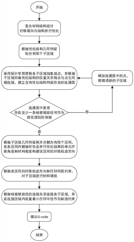
[0035] refer to figure 1 , a continuous fiber 3D printing path planning method for parallel optimization of fiber orientation and structure, comprising the following steps:

[0036] 1) Construct a parallel optimization model of fiber orientation and composite material structure, taking material density x and fiber angle θ as design variables, and its mathematical model is as follows:

[0037]

[0038]

[0039] In the formula, the objective function c represents the minimum compliance value; U and F represent the global displacement vector and the global load vector respectively; K represents the global stiffness matrix; u e and k e represent the element displacement vector and the element stiffness matrix respectively; x min Represents the relative minimum density; p represents the penalty factor; N represents the number of finite element gr...


PUM


Abstract

The invention discloses a continuous fiber 3D printing path planning method capable of achieving fiber orientation and structure parallel optimization. The method comprises the steps that a fiber orientation and composite material structure parallel optimization model is constructed, material density and a fiber angle serve as design variables, and the material density and the fiber angle are filtered to obtain a fiber orientation and composite material structure parallel optimization structure; a complex optimization structure is dispersed into a structure in a simple geometrical shape, each sub-region is abstracted into points by adopting a topology thought, the points are connected according to a position relation of an optimization structure to which the sub-regions belong, a connected graph containing optimization structure feature information is formed, and path planning classified into a Hamiltonian path for searching in the connected graph; a material density value is taken as a weight factor of the fiber angle to obtain a fiber track direction in each sub-region of the optimized structure; and printing paths of the sub-regions are connected in sequence according to a Hamiltonian path to generate a printing code. The anisotropic mechanical property of a continuous fiber reinforced composite material is exerted, and the requirement of the 3D printing process is met.

Description

technical field [0001] The invention belongs to the technical fields of structural optimization, composite materials and additive manufacturing, and specifically relates to a continuous fiber 3D printing path planning method for parallel optimization of fiber orientation and structure. [0002] technical background [0003] Continuous fiber reinforced composites, as an anisotropic material, are important materials for the manufacture of advanced structures. The 3D printing process of continuous fiber-reinforced composites breaks the constraints of traditional molding and laying technology on the fiber angle direction, and prints the model with path planning information, which can realize fine control and free design of fiber orientation. Using the similar principle of fused deposition modeling (FDM) technology, the fiber dry filament and thermoplastic filament are impregnated online and printed through the printing nozzle, and its mechanical properties change according to the...

Claims


Application Information

Patent Timeline
Patent Type & Authority Applications(China)
IPC IPC(8): B29C64/386G06F30/20B33Y50/00G06F113/10G06F113/26
CPCB29C64/386G06F30/20B33Y50/00G06F2113/10G06F2113/26
Inventor 田小永黄一鸣郑子琪李武丹
Owner XI AN JIAOTONG UNIV
Why Eureka
Try Eureka