Double-source integrated air source heat pump unit with total heat recovery function

An air source heat pump and total heat recovery technology, applied in the direction of heat recovery system, heat pump, machine operation, etc., can solve the problems of summer cooling, large pressure drop of components and pipelines, unit cooling capacity and cooling energy efficiency attenuation, etc. problems, to achieve the effect of improving energy utilization efficiency and cooling energy efficiency

Active Publication Date: 2021-09-28
ZHEJIANG KING CO LTD
View PDF6 Cites 2 Cited by
  • Summary
  • Abstract
  • Description
  • Claims
  • Application Information

AI Technical Summary

Problems solved by technology

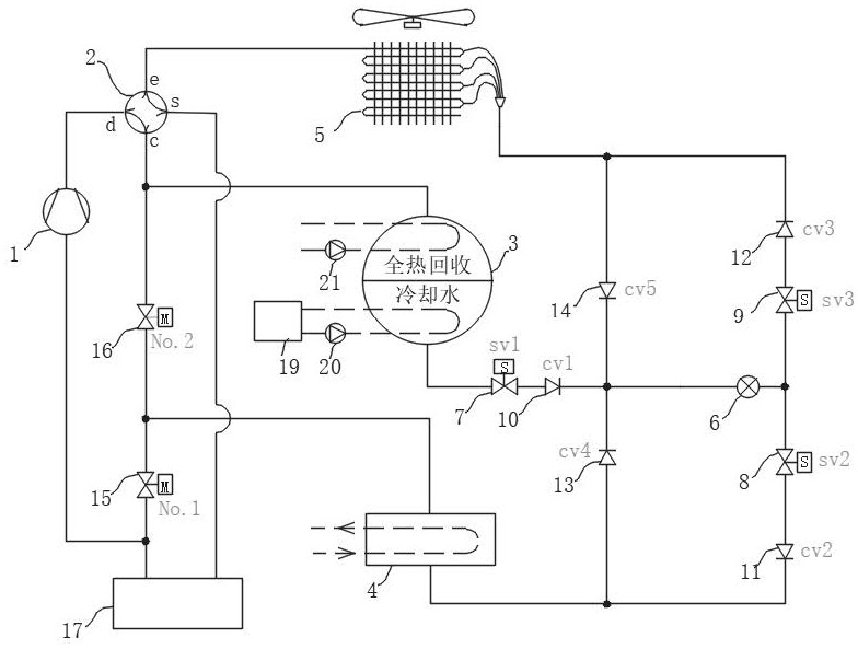
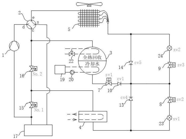
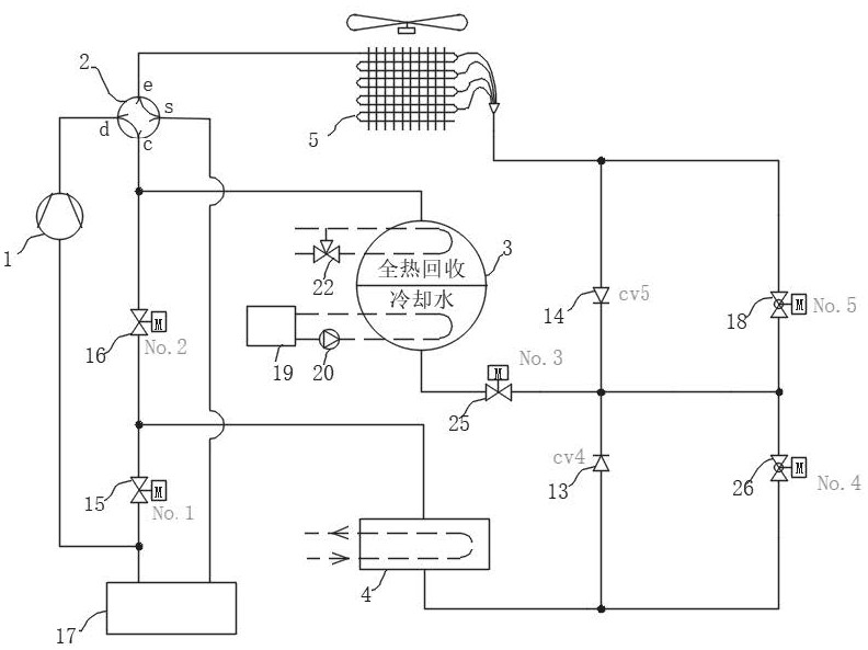
[0010] In order to overcome the fact that the existing heat pump air conditioners cannot have the functions of cooling in summer, heating in winter, and process / sanitary hot water preparation, the dual-source integrated air source heat pump unit with full heat recovery of the present invention optimizes the circulation process of the refrigeration system, Refrigeration adopts water cooling, the condensing temperature can be reduced by about 14°C compared with the air-cooled heat pump, which can significantly improve the cooling capacity and cooling energy efficiency of the unit, and the low-pressure gas from the shell-and-tube heat exchanger (4) directly enters the suction port of the compressor, It can effectively overcome the need for conventional air-cooled heat pump units to flow through the four-way valve, the gas-liquid separator, and then enter the suction port of the compressor, causing excessive pressure drop of low-pressure suction side components and pipelines, resulting in attenuation of cooling capacity and cooling energy efficiency of the unit The air source heat pump is used for heating in winter, and it has the function of heat recovery to provide process or sanitary hot water throughout the year

Method used


Image

  • Double-source integrated air source heat pump unit with total heat recovery function
  • Double-source integrated air source heat pump unit with total heat recovery function
  • Double-source integrated air source heat pump unit with total heat recovery function

Examples


Embodiment Construction

[0030] Embodiments of the present invention are described in detail below, examples of which are shown in the drawings, wherein the same or similar reference numerals designate the same or similar elements or elements having the same or similar functions throughout. The embodiments described below by referring to the figures are exemplary and are intended to explain the present invention and should not be construed as limiting the present invention.

[0031] In the description of the present invention, it should be understood that the terms "first" and "second" are used for description purposes only, and cannot be interpreted as indicating or implying relative importance or implicitly indicating the quantity of indicated technical features. Thus, a feature defined as "first" and "second" may explicitly or implicitly include one or more of these features. In the description of the present invention, "plurality" means two or more, such as two, three, etc., unless otherwise speci...


PUM


Abstract

The invention relates to the technical field of heat pump machinery, in particular to a double-source integrated air source heat pump unit with a total heat recovery function. A high-pressure outlet of a compressor of the heat pump unit is connected with a connector d of the four-way reversing valve, an connector c is connected with the composite water-cooled condenser, a connector e is connected with the finned heat exchanger, and a connector s is connected with an inlet of the gas-liquid separator. An outlet of the composite water-cooling condenser is connected with the shell and tube heat exchanger and a liquid side connector of the finned heat exchanger through pipelines and valves; a gas side connector of the shell and tube heat exchanger is connected with an inlet of the compressor through pipelines and valves; an outlet of the gas-liquid separator is connected with an air suction port of the compressor through a pipeline. Free switching of operation modes such as refrigeration, heating, refrigeration and total heat recovery and hot water can be achieved, the requirements of buildings or industrial projects for refrigeration, heating and hot water all year round are met, and therefore, the multiple purposes of one machine are achieved, and the cost is effectively saved.

Description

technical field [0001] The invention relates to the technical field of heat pump machinery, in particular to a dual-source integrated air source heat pump unit with full heat recovery. Background technique [0002] Conventional central air-conditioning host generally adopts the following two methods: [0003] 1) Water-cooled chiller [0004] When cooling, the water-cooled chiller unit provides 7°C chilled water to the air-conditioning terminal such as the fan coil to cool the air in the room. The water-cooled condenser transfers the condensation heat of the high-temperature and high-pressure refrigerant to the cooling water, and the cooling water is sent to Cooling towers reject heat to the outside atmosphere. Usually, the water-cooled chiller is placed indoors, and the cooling tower is placed outdoors. There is a long cooling water circulation pipeline between the two, which requires a high-power and high-lift cooling water pump to drive the cooling water circulation; and...

Claims


Application Information

Patent Timeline
Patent Type & Authority Applications(China)
IPC IPC(8): F25B29/00F25B30/02F25B41/20F25B41/30F25B49/02
CPCF25B29/003F25B30/02F25B41/20F25B41/30F25B49/02Y02B30/52
Inventor 唐进军章立标韩伟达金成召经武辉顾君丰
Owner ZHEJIANG KING CO LTD
Why Eureka
Try Eureka