Novel airtight tile type phased array antenna

A phased array antenna and tile-type technology, which is applied to antennas, antenna arrays, antenna components, etc., can solve the problems of small volume, high air tightness, and inability to meet manufacturability at the same time, and achieve reduced volume and small volume , good anti-vibration effect

Active Publication Date: 2021-09-28
成都雷电微力科技股份有限公司
View PDF15 Cites 4 Cited by
  • Summary
  • Abstract
  • Description
  • Claims
  • Application Information

AI Technical Summary

Problems solved by technology

[0009] The purpose of the present invention is to provide a new type of airtight tile-type phased array antenna to solve the problem that the existing brick-type and tile-type phased array antennas cannot simultaneously meet the requirements of manufacturability and high air-tightness. Density, small size, light weight requirements

Method used


Image

  • Novel airtight tile type phased array antenna
  • Novel airtight tile type phased array antenna
  • Novel airtight tile type phased array antenna

Examples


Embodiment 1

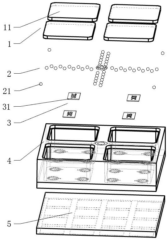
[0038] See attached figure 1 , figure 2 , the new airtight tile-type phased array antenna includes a cover layer 1, a ball planting layer 2, a radio frequency chip layer 3, a dielectric cavity layer 4 and an array antenna layer 5 from the RF input side to the RF output side. The structure of each layer Layer by layer settings.

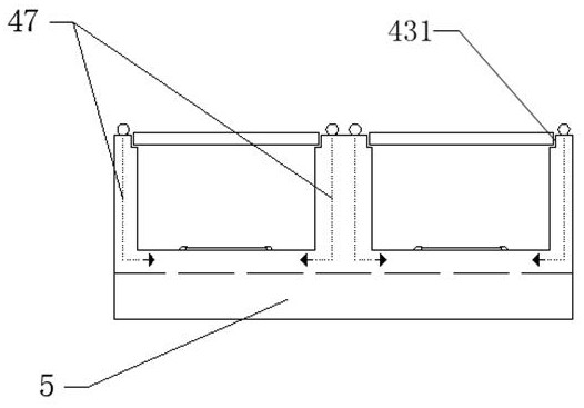
[0039] The dielectric chamber layer 4 includes a plurality of concave slots 43 , and each slot 43 is arranged in an array. A radio frequency link 48 for transmitting radio frequency signals and a low frequency link 47 for transmitting power and control signals are arranged in the dielectric cavity layer 4 .

[0040] The cover layer 1 seals each slot 43 , and leaves an exposed space between adjacent slots 43 for the design of the ball planting layer 2 , that is, the ball planting layer 2 is not covered by the cover layer 1 . On the medium cavity layer 4 , a step 431 can be designed at the position for installing the cover layer 1 , the cover layer 1...

Embodiment 2

[0045] This embodiment discloses a new type of airtight tiled phased array antenna, which is roughly the same in design as the first embodiment, the only difference is that this embodiment further designs the access of the radio frequency link 48 .

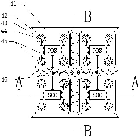
[0046] like figure 2 As shown, in this embodiment, the radio frequency link 48 is connected at the center of the dielectric cavity layer 4 . In some embodiments, a radio frequency access transition structure 46 is provided at the center of the dielectric cavity layer 4 (or other positions), and a plurality of implanted balls 21 are provided on the surface of the radio frequency access transition structure 46 , and the radio frequency access transition structure 46 It is connected to the radio frequency link 48 inside the dielectric cavity layer 4 .

Embodiment 3

[0048] This embodiment discloses a new type of airtight tiled phased array antenna, which is roughly the same in design as the first embodiment. The only difference is that this embodiment further designs the access of the low-frequency link 47 .

[0049] like figure 2 , 3 As shown, in this embodiment, the dielectric cavity layer 4 and the area between the adjacent slots 43 are densely covered with balls 21 , and some or all of these balls 21 are connected to the low frequency in the dielectric cavity layer 4 . link 47.

[0050] If the grooves 43 have adjacent grooves 43 in both the lateral and longitudinal directions, the ball-mounting 21 is provided on at least one adjacent side of the grooves 43 . For example, if a slot 43 has adjacent slots 43 in both the horizontal and vertical directions, the ball mount 21 used to provide power and control signals for the RF chip 31 in the slot 43 can be arranged in the slot 43 adjacent to the slot 43 in the longitudinal direction. T...


PUM


Abstract

The invention discloses a novel airtight tile type phased array antenna. The radio frequency chips are arranged in the slots of the dielectric cavity layer one by one, the slots are sealed by the cover plate layer, the dielectric cavity layer is connected with the array antenna layer on the back surfaces of the slots, and the radio frequency chips are connected with the array antenna layer. A ball mounting layer is arranged on the dielectric cavity layer and around the slots, and the ball mounting layer is connected with each radio frequency chip through a radio frequency link and a low frequency link. A micro-channel is designed in the medium cavity layer, and heat generated by the radio frequency chip is conducted to the ball mounting layer through the micro-channel. Compared with an existing tile-type or brick-type phased array antenna, the phased array antenna is smaller in size, lighter in weight and thinner in thickness, can be directly produced and assembled through an SMT automatic labeling process, and is high in production efficiency. According to the invention, the use of connectors is reduced, and the high airtightness requirement can be realized.

Description

technical field [0001] The invention relates to the field of wireless communication equipment, in particular to a novel airtight tile-type phased array antenna. Background technique [0002] The phased array antenna is the key core component of the phased array radar / communication system, which directly determines the performance of the entire phased array radar / communication system, and occupies a large proportion in the cost, volume, weight and power consumption of the entire system . The architecture of active phased array antennas can be roughly divided into two types: brick type and tile type according to the circuit assembly method. Brick-type active phased array antennas are simple in design, easy to install, and have strong heat dissipation capabilities, but they are heavy and bulky, which limits the development and application of active phased array antennas to some extent. The tile active phased array antenna is highly integrated and usually adopts a stacked stru...

Claims


Application Information

Patent Timeline
Patent Type & Authority Applications(China)
IPC IPC(8): H01Q1/00H01Q1/02H01Q1/36H01Q1/50H01Q21/00H01Q23/00
CPCH01Q1/005H01Q1/02H01Q1/36H01Q1/50H01Q21/0006H01Q23/00
Inventor 薛伟丁卓富阴明勇周沛瀚符博
Owner 成都雷电微力科技股份有限公司
Why Eureka
Try Eureka