This helps you quickly interpret patents by identifying the three key elements:
Problems solved by technology
Method used
Benefits of technology
Problems solved by technology
[0009] The purpose of the present invention is to provide a new type of airtight tile-type phased array antenna to solve the problem that the existing brick-type and tile-type phased array antennas cannot simultaneously meet the requirements of manufacturability and high air-tightness. Density, small size, light weight requirements
Method used
Image
Click on the blue label to locate the original text in one second.
Reading with bidirectional positioning of images and text.
Examples
Embodiment 1
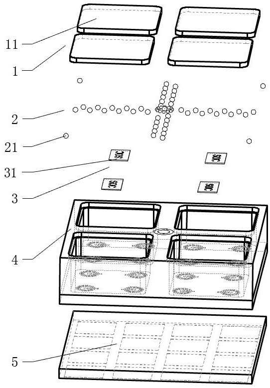
[0038] See attached figure 1 , figure 2 , the new airtight tile-type phased array antenna includes a cover layer 1, a ball planting layer 2, a radio frequency chip layer 3, a dielectric cavity layer 4 and an array antenna layer 5 from the RF input side to the RF output side. The structure of each layer Layer by layer settings.
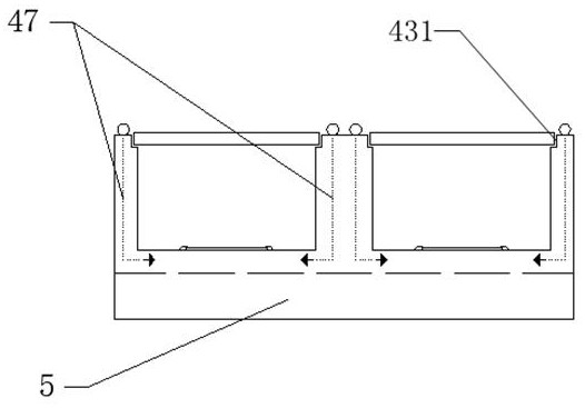
[0039] The dielectric chamber layer 4 includes a plurality of concave slots 43 , and each slot 43 is arranged in an array. A radio frequency link 48 for transmitting radio frequency signals and a low frequency link 47 for transmitting power and control signals are arranged in the dielectric cavity layer 4 .
[0040] The cover layer 1 seals each slot 43 , and leaves an exposed space between adjacent slots 43 for the design of the ball planting layer 2 , that is, the ball planting layer 2 is not covered by the cover layer 1 . On the medium cavity layer 4 , a step 431 can be designed at the position for installing the cover layer 1 , the cover layer 1...
Embodiment 2
[0045] This embodiment discloses a new airtight tile-type phased array antenna, which is roughly the same in design as in Embodiment 1, the only difference being that the access of the radio frequency link 48 is further designed in this embodiment.
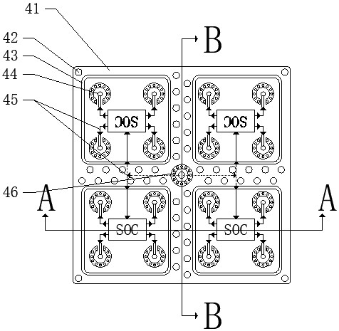
[0046] Such as figure 2 As shown, in this embodiment, the radio frequency link 48 is connected at the center of the dielectric cavity layer 4 . In some embodiments, a radio frequency access transition structure 46 is provided at the center of the dielectric cavity layer 4 (or other positions), and several planting balls 21 are arranged on the surface of the radio frequency access transition structure 46, and the radio frequency access transition structure 46 It is connected with the radio frequency link 48 inside the dielectric cavity layer 4 .
Embodiment 3
[0048] This embodiment discloses a new airtight tile-type phased array antenna, which is roughly the same in design as Embodiment 1, the only difference being that the access of the low-frequency link 47 is further designed in this embodiment.
[0049] Such as figure 2 , 3 As shown, in this embodiment, on the dielectric cavity layer 4 and the area between adjacent slots 43, there are densely planted balls 21, and some or all of these planted balls 21 are connected to the low frequency in the dielectric cavity layer 4. Link 47.
[0050] If the slot 43 has adjacent slots 43 in both the transverse direction and the longitudinal direction, the ball planting 21 is arranged on at least one adjacent side of the slot 43 . For example, if a slot 43 has adjacent slots 43 both horizontally and vertically, the ball planting 21 for providing power and control signals to the radio frequency chip 31 in this slot 43 can be arranged in the slot 43 adjacent to the vertical direction. The ad...
PUM
Abstract
The invention discloses a novel airtight tile type phased array antenna. The radio frequency chips are arranged in each slot of the dielectric cavity layer one by one, the cover plate layer seals each slot, the dielectric cavity layer is connected to the array antenna layer on the back of the slot, and the radio frequencychip is connected to the array antenna layer. A ball-planting layer is arranged on the dielectric cavity layer and around the slot, and the ball-planting layer is connected to each radio frequencychip through a radio frequency link and a low frequency link. A micro-channel is designed in the dielectric cavity layer, and the micro-channel conducts the heat generated by the radio frequency chip to the ball-planting layer. Compared with the existing tile-type or brick-type phased array antennas, the phased array antenna of the present invention is smaller in volume, lighter in weight and thinner in thickness, can be directly produced and assembled through the SMT automatic labeling process, and has high production efficiency. The invention reduces the use of connectors and can achieve high airtight requirements.
Description
technical field [0001] The invention relates to the field of wireless communication equipment, in particular to a novel airtight tile-type phased array antenna. Background technique [0002] The phased array antenna is the key core component of the phased array radar / communication system, which directly determines the performance of the entire phased array radar / communication system, and occupies a large proportion in the cost, volume, weight and power consumption of the entire system . The architecture of active phased array antennas can be roughly divided into two types: brick type and tile type according to the circuit assembly method. Brick-type active phased array antennas are simple in design, easy to install, and have strong heat dissipation capabilities, but they are heavy and bulky, which limits the development and application of active phased array antennas to some extent. The tile active phased array antenna is highly integrated and usually adopts a stacked stru...
Claims
Application Information
Patent Timeline
Application Date:The date an application was filed.
Publication Date:The date a patent or application was officially published.
First Publication Date:The earliest publication date of a patent with the same application number.
Issue Date:Publication date of the patent grant document.
PCT Entry Date:The Entry date of PCT National Phase.
Estimated Expiry Date:The statutory expiry date of a patent right according to the Patent Law, and it is the longest term of protection that the patent right can achieve without the termination of the patent right due to other reasons(Term extension factor has been taken into account ).
Invalid Date:Actual expiry date is based on effective date or publication date of legal transaction data of invalid patent.

