
Unmanned aerial vehicle, control method and device thereof, remote control terminal and unmanned aerial vehicle system

A technology of remote control terminal and control method, applied in the field of unmanned aerial vehicle, can solve the problems of lack of control experience, bombing, loss of control, etc., and achieve the effect of reducing the difficulty of control and improving the flight experience

Pending Publication Date: 2021-09-28
SZ DJI TECH CO LTD
View PDF0 Cites 1 Cited by
  • Summary
  • Abstract
  • Description
  • Claims
  • Application Information

AI Technical Summary

Problems solved by technology

However, for many users, in the manual control mode, due to lack of experience in manipulation, it is difficult to manually control the traversing machine to maintain a stable state
Especially beginners generally need to practice for a long time on the simulator to have a better control perception. If they are not sensitive to the attitude control of the traversing machine, they will easily cause loss of control or even Fryer

Method used


Image

  • Unmanned aerial vehicle, control method and device thereof, remote control terminal and unmanned aerial vehicle system
  • Unmanned aerial vehicle, control method and device thereof, remote control terminal and unmanned aerial vehicle system
  • Unmanned aerial vehicle, control method and device thereof, remote control terminal and unmanned aerial vehicle system

Examples


Embodiment 1

[0069] Embodiment 1 and Embodiment 2 will describe in detail the implementation process of the UAV control method according to the embodiment of the present application from the side of the UAV and the side of the remote control terminal respectively.

[0070] Embodiment one

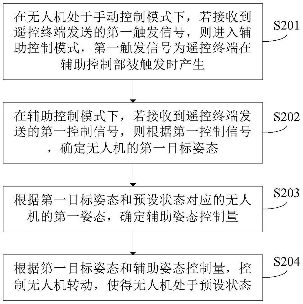
[0071] figure 2 It is a schematic flow chart of the UAV control method on the UAV side in an embodiment of the present application; the execution subject of the UAV control method in this embodiment can be the flight controller of the UAV, or it can be Other controllers installed on the drone. In this embodiment, it is taken that the execution subject of the control method of the UAV is the flight controller as an example. See figure 2 , The method for controlling a drone in this embodiment may include S201-S204.

[0072] Wherein, in S201, when the UAV is in the manual control mode, if it receives the first trigger signal sent by the remote control terminal, it enters the auxiliary control mode. Th...

Embodiment 2

[0109] Figure 5 It is a schematic diagram of the method flow of the control method of the drone in an embodiment of the present application on the remote control terminal side; other controllers on the terminal. See Figure 5 , the method for controlling the drone in this embodiment may include S501-S503.

[0110] Wherein, in S501, a first user instruction is obtained, and the first user instruction is used to instruct switching the auxiliary control unit from a non-triggered state to a triggered state.

[0111] The first user instruction may include an operation instruction for the user to operate (such as single click, double click or long press) the auxiliary control part when the auxiliary control device is in a non-triggered state. Exemplarily, when the auxiliary control device is in the non-triggering state, the user clicks the auxiliary control part, and the triggering auxiliary control device is switched from the non-triggering state to the triggering state.

[01...

Embodiment 3

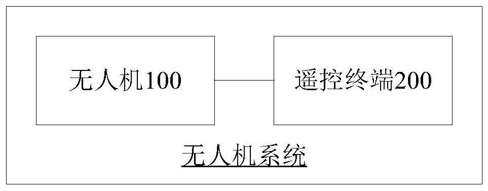
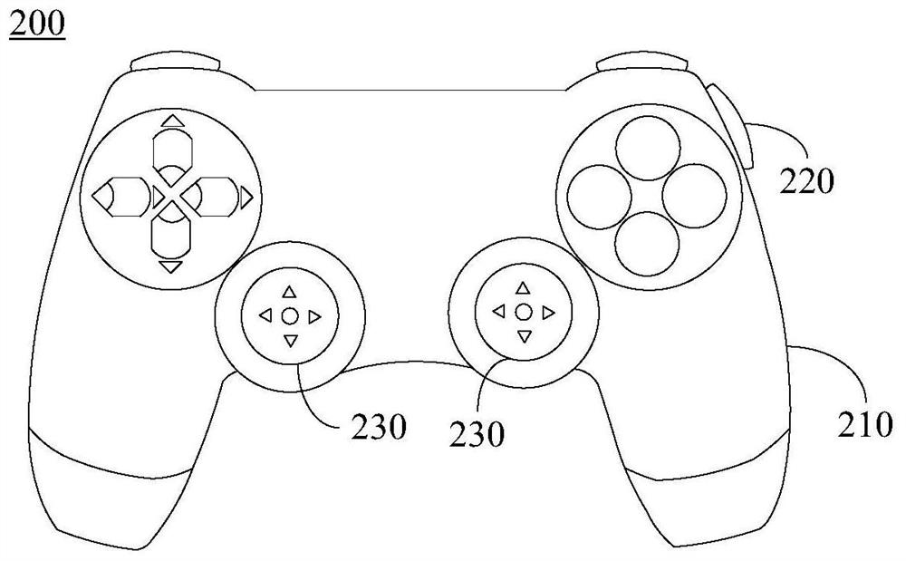
[0135] The embodiment of this application provides an unmanned aerial vehicle system, please refer to Figure 1A and Figure 1B , the drone system may include a drone 100 and a remote control terminal 200 communicatively connected to the drone 100 , and the remote control terminal 200 may include an auxiliary control unit 220 .

[0136] Wherein, the remote control terminal 200 is configured to switch the auxiliary control unit 220 from the non-triggering state to the triggering state when acquiring the first user instruction indicating to switch the auxiliary control unit 220 from the non-triggering state to the triggering state, and generate the first trigger Signal; sending a first trigger signal to the UAV 100 .

[0137] The UAV 100 is used to enter the auxiliary control mode if the UAV 100 is in the manual control mode and receives the first trigger signal sent by the remote control terminal 200; The first control signal, then according to the first control signal, determ...


PUM


Abstract

An unmanned aerial vehicle, a control method and device thereof, a remote control terminal, and an unmanned aerial vehicle system are disclosed, the unmanned aerial vehicle system comprising an unmanned aerial vehicle (100) and a remote control terminal (200). The remote control terminal (200) is used for switching an auxiliary control part (220) of the remote control terminal from a non-trigger state to a trigger state when a first user instruction indicating that the auxiliary control part (220) is switched from the non-trigger state to the trigger state is obtained, and generating a first triggering signal; the first trigger signal is sent to the unmanned aerial vehicle (100); the unmanned aerial vehicle (100) is configured, when the unmanned aerial vehicle (100) is in a manual control mode, to enter an auxiliary control mode (S201) if a first trigger signal sent by the remote control terminal (200) is received; in the auxiliary control mode, if a first control signal transmitted by the remote control terminal (200) is received, a first target attitude of the unmanned aerial vehicle (100) is determined according to the first control signal (S202); an auxiliary attitude control quantity is determined according to the first target attitude and a first attitude of the unmanned aerial vehicle (100) corresponding to the preset state (S203); and the unmanned aerial vehicle (100) is controlled to rotate according to the first target attitude and the auxiliary attitude control quantity, so that the unmanned aerial vehicle (100) is in a preset state (S204).

Description

technical field [0001] The present application relates to the field of unmanned aerial vehicles, in particular to an unmanned aerial vehicle and its control method and device, a remote control terminal, and an unmanned aerial vehicle system. Background technique [0002] At present, some drones provide different working modes for users to choose, so that users can obtain different control experiences. For example, the working modes of the flying machine include self-stabilizing mode and manual control mode. In the self-stabilizing mode, the flight controller of the flying machine will control the attitude of the flying machine autonomously, so that the flying machine remains in a stable state; in the manual control mode In this case, the user needs to manually operate the joystick of the remote control to control the attitude of the traversing machine, so that the traversing machine remains in a stable state. Specifically, the attitude of the traversing machine is controlled...

Claims


Application Information

Patent Timeline
Patent Type & Authority Applications(China)
IPC IPC(8): G05D1/08G05D1/10
CPCG05D1/0808G05D1/101G05D1/08G05D1/10G05D1/00
Inventor 黄敏
Owner SZ DJI TECH CO LTD
Learn More