Supercharge Your Innovation With Domain-Expert AI Agents!

Liquid three-way connector for liposuction swelling liquid injection

A three-way connector and swelling fluid technology, which is applied in the direction of subcutaneous injection devices, devices introduced into the body, instruments, etc., can solve the problems of cumbersome operation process and increased infection risk, and achieve simple operation, uniform flow rate and controllable flow rate Effect

Inactive Publication Date: 2021-10-01
曾志权
View PDF19 Cites 0 Cited by
  • Summary
  • Abstract
  • Description
  • Claims
  • Application Information

AI Technical Summary

Problems solved by technology

[0003] Injection of swelling fluid in traditional liposuction requires a metal submersible head to be placed in an open container and injected by driving a pump. Liquid three-way connector for surgical swelling fluid injection

Method used


Image

  • Liquid three-way connector for liposuction swelling liquid injection
  • Liquid three-way connector for liposuction swelling liquid injection
  • Liquid three-way connector for liposuction swelling liquid injection

Examples


Embodiment 1

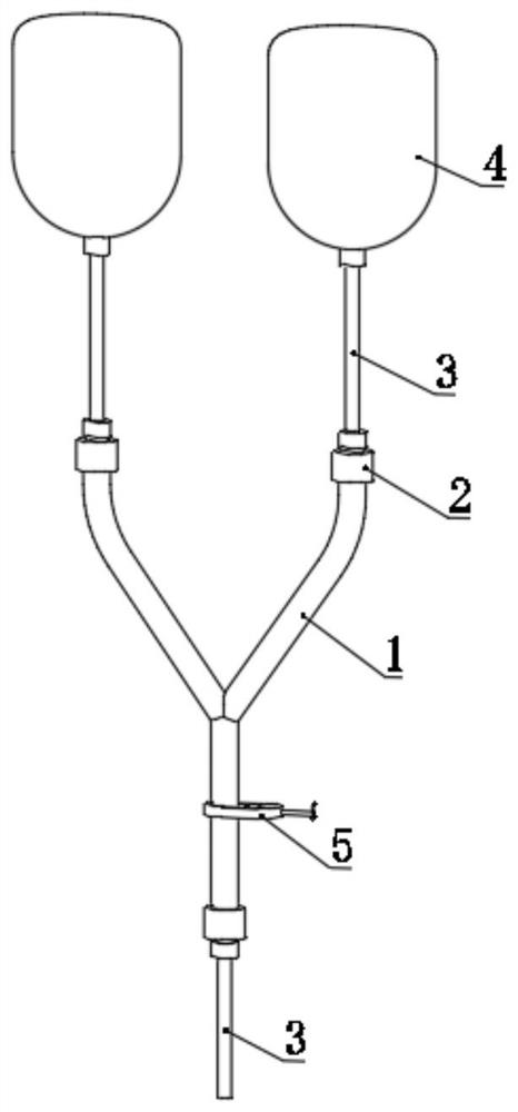
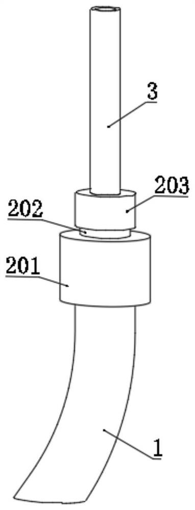
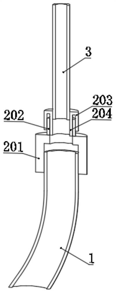
[0027] refer to Figure 1-3 , a liquid three-way connector for swelling fluid injection in liposuction operation, comprising a three-way connection tube 1, the three-way connection tube 1 includes two liquid inlet ends and one liquid outlet end, the liquid inlet end of the three-way connection pipe 1 and The liquid outlets are detachably installed with the infusion pipeline 3 through the connector 2, the infusion pipeline 3 is connected with the container bottle 4, the connector 2 includes a connecting pipe 201, the connecting pipe 201 is fixed to the end of the three-way connecting pipe 1, and the connecting pipe 201 The side away from the tee connecting pipe 1 is fixed with an internal and external double threaded pipe 202, and the side of the internal and external double threaded pipe 202 away from the connecting pipe 201 is threaded with the internal threaded pipe 203 and the external threaded pipe 204, and the internal threaded pipe 203 and the external threaded pipe 204 ...

Embodiment 2

[0031] refer to Figure 1-5 In the second embodiment, on the basis of the first embodiment above, a flow controller 5 is installed at the position of the three-way connecting pipe 1 close to the liquid outlet, and the flow controller 5 includes a ring body sleeved on the outside of the three-way connecting pipe 1 501, the inner wall of the ring body 501 is slidingly provided with an extruding plate 502, the ring body 501 is a track-shaped structure formed by two semicircular segments and two straight segments, and the extruding plate 502 is a semicircular plate-shaped structure. Slide bars 505 are fixed on both sides of the extrusion plate 502 , and slide grooves 506 matching the slide bars 505 are provided on the inner wall of the ring body 501 . A threaded rod 503 is rotatably installed on the side of the extruding plate 502 away from the tee connecting pipe 1 , and a threaded hole matching the threaded rod 503 is opened on the side of the ring body 501 close to the threaded...


PUM

PropertyMeasurementUnit
The inside diameter ofaaaaaaaaaa
Outer diameteraaaaaaaaaa
The inside diameter ofaaaaaaaaaa

Abstract

The invention discloses a liquid three-way connector for liposuction swelling liquid injection, and belongs to the field of liposuction swelling liquid injection. The liquid three-way connector comprises a three-way connecting pipe, the three-way connecting pipe comprises two liquid inlet ends and a liquid outlet end, and the liquid inlet ends and the liquid outlet end of the three-way connecting pipe are detachably installed on a transfusion pipeline through connectors; the transfusion pipeline is connected with a container bottle, the connector comprises a connecting pipe, and the connecting pipe is fixed with the end part of the three-way connecting pipe. Under the condition that swelling liquid in the container bottle does not make contact with air, the swelling liquid flows into the three-way connecting pipe through the liquid conveying pipeline according to the pressure fall principle and is finally injected into the human body through the transfusion pipeline, full-closed injection is achieved in the injection process, the flow speed is uniform and controllable in the injection process, and therefore operation is simpler.

Description

technical field [0001] The invention relates to the technical field of swelling fluid injection for liposuction surgery, in particular to a liquid three-way connector for swelling fluid injection for liposuction surgery. Background technique [0002] Liposuction is one of the surgical body sculpting operations. The principle is to suck out excess fat from a certain part of the body through negative pressure suction, so as to achieve the purpose of local rapid slimming. The common parts of body liposuction are: face, double chin, neck, shoulders, limbs, hands and feet, upper and lower abdomen, side waist, upper buttocks, buttock reduction and buttock lift, etc. [0003] Injection of swelling fluid in traditional liposuction requires a metal submersible head to be placed in an open container and injected by driving a pump. Liquid three-way connector for surgical swelling fluid injection. Contents of the invention [0004] The purpose of the present invention is to solve th...

Claims


Application Information

Patent Timeline
IPC IPC(8): A61M39/10A61M5/14A61M5/168
CPCA61M39/10A61M5/16877A61M5/16813A61M5/14A61M2039/1033
Inventor 曾志权
Owner 曾志权
Features
  • R&D
  • Intellectual Property
  • Life Sciences
  • Materials
  • Tech Scout
  • Unparalleled Data Quality
  • Higher Quality Content
  • 60% Fewer Hallucinations
Learn More