Optical fiber laser cutting machine

A laser cutting machine, fiber laser technology, applied in the direction of laser welding equipment, welding equipment, metal processing equipment, etc., can solve the problems of metal block falling off, metal block falling on the surface of the support frame, time waste, etc., and achieve the effect of avoiding waste

Inactive Publication Date: 2021-10-01
深圳市大鹏激光科技有限公司
View PDF0 Cites 4 Cited by
  • Summary
  • Abstract
  • Description
  • Claims
  • Application Information

AI Technical Summary

Problems solved by technology

[0003] However, the existing fiber laser cutting machine still has some shortcomings during use. For example, after the existing fiber laser cutting machine finishes cutting the metal plate, the cut metal block will fall off inside the metal plate, and the metal The block will fall to the surface of the support frame, and the metal block cannot be completely separated from the metal plate, resulting in the cut metal block, which needs to wait until the fiber laser cutting machine stops running before the metal block can be picked up, so that the cut metal block cannot be picked up. The metal block quickly enters the processing of the next process and causes a waste of time, so a fiber laser cutting machine is needed to solve the problems raised above

Method used


Image

  • Optical fiber laser cutting machine
  • Optical fiber laser cutting machine
  • Optical fiber laser cutting machine

Examples


Embodiment 1

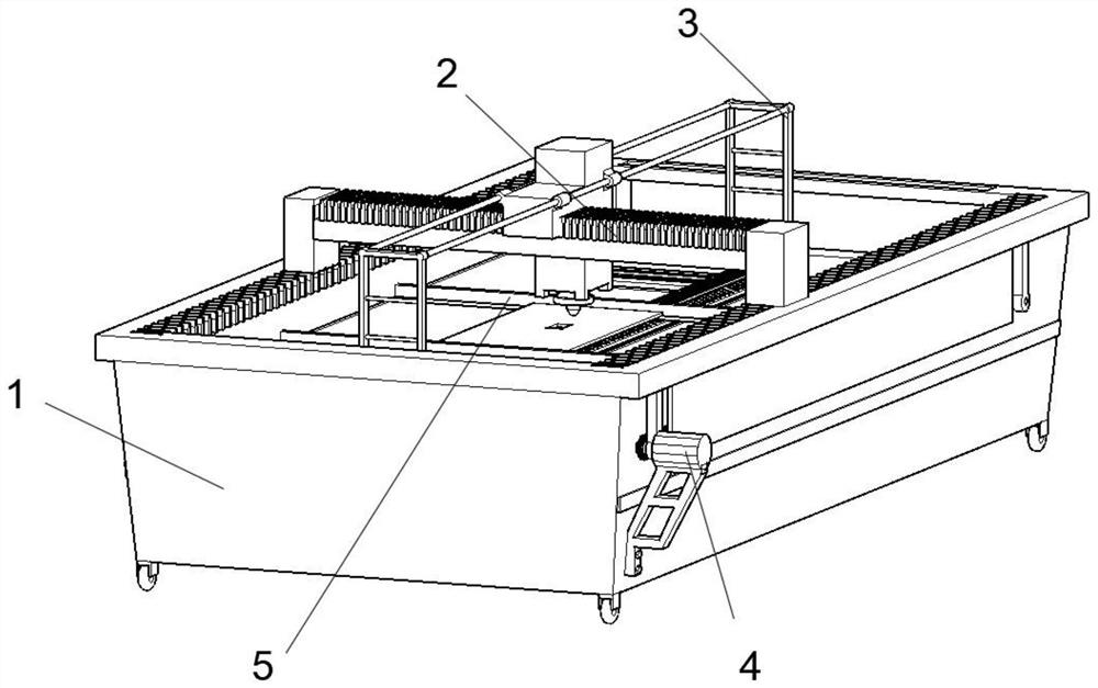
[0031] see Figure 1-6 , an embodiment provided by the present invention: a fiber laser cutting machine, including a laser cutting machine 1, a fiber laser cutting device 2, a conveying device 3, a driving device 4 and a clamping plate 5, and the fiber laser cutting device 2 is slidably installed on Inside the top end of the laser cutting machine 1, the conveying device 3 is slidably installed inside the laser cutting machine 1 and on the outer surface of the fiber laser cutting device 2, and the driving device 4 is fixedly installed on the inner center peripheral edge of the laser cutting machine 1, and the clamping plate 5 is slidably installed inside the laser cutting machine 1;

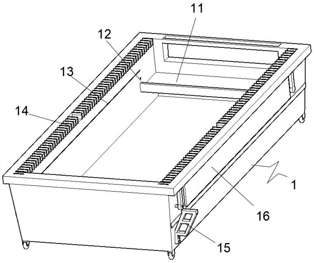
[0032] The interior of the laser cutting machine 1 includes a collection table 11, a limit shaft hole 12, a limit slideway 13, a dust-proof folding cloth 14, a support frame 15 and a protective side plate 16. The limit slideway 13 is set symmetrically on the laser cutting machine 1. In the center...

Embodiment 2

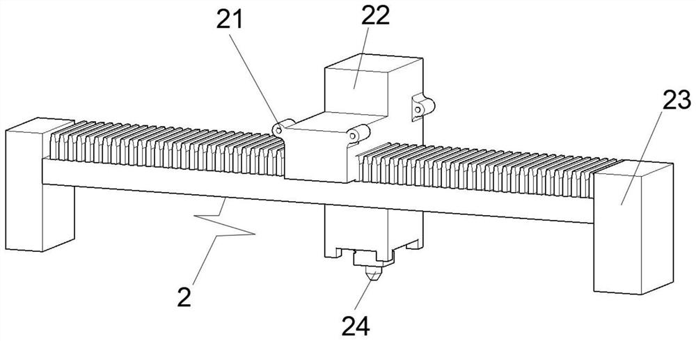
[0041] On the basis of Example 1, such as Figure 7-8 As shown, the central edge of the bottom surface of the cutter 22 is slidably installed with an auxiliary blanking device 25. The interior of the auxiliary blanking device 25 includes a plug-in post 251, a hoop 252, a buffer spring 253 and a rubber block 254, and the plug-in post 251 is evenly welded. On the outer surface of the hoop 252 , a rubber block 254 is fixedly connected to the center of the bottom surface of the insertion post 251 , and the buffer spring 253 is sleeved on the outer surface of the insertion post 251 .

[0042] When this embodiment is implemented, after the laser cutting head 24 cuts the metal plate, it will descend downwards, and the laser cutting head 24 will drive the auxiliary blanking device 25 to descend at the same time, because the bottom end of the auxiliary blanking device 25 is lower than the laser The bottom of the cutting head 24, so when the laser cutting head 24 descends, it will drive...


PUM


Abstract

The invention discloses an optical fiber laser cutting machine. The optical fiber laser cutting machine comprises a laser cutting machine body, an optical fiber laser cutting device, a conveying device, a driving device and clamping plates; the optical fiber laser cutting device is slidably installed in the top end of the laser cutting machine body; the conveying device is slidably mounted in the laser cutting machine body and located on the outer surface of the optical fiber laser cutting device; the driving device is fixedly mounted on the peripheral edge of the center in the laser cutting machine body; and the clamping plates are slidably mounted in the laser cutting machine body. The laser cutting machine body internally comprises a collecting table, limiting shaft holes, limiting sliding ways, dustproof folding cloth, a supporting frame and protective side plates, and the limiting sliding ways are symmetrically formed in the centers of the two sides of the interior of the laser cutting machine body. According to the optical fiber laser cutting machine, the conveying device synchronously slides along with the optical fiber laser cutting device, cut metal blocks can be synchronously conveyed, therefore, the cut metal blocks quickly enter the next procedure, and time waste is avoided.

Description

technical field [0001] The invention relates to the technical field of fiber laser cutting machine equipment, in particular to a fiber laser cutting machine. Background technique [0002] Fiber laser cutting machine can be used for both plane cutting and bevel cutting, and the edges are neat and smooth. It is suitable for high-precision cutting processing such as metal plates. At the same time, the mechanical arm can perform three-dimensional cutting instead of the original imported five Axis laser, compared with ordinary carbon dioxide laser cutting machine, saves space and gas consumption, and has a high photoelectric conversion rate. The nozzle sprays non-oxidizing gas and relies on the strong pressure of the gas to remove the liquid metal and form a slit. When the fiber laser cutting machine is in use, it is mainly used for cutting some materials that are not easy to oxidize or active metals, such as stainless steel, titanium, aluminum and others. its alloy etc. [000...

Claims


Application Information

Patent Timeline
Patent Type & Authority Applications(China)
IPC IPC(8): B23K26/38B23K26/08B23K26/70
CPCB23K26/38B23K26/0876B23K26/702
Inventor 汤鹏飞
Owner 深圳市大鹏激光科技有限公司
Why Eureka
Try Eureka