Mirror surface polishing equipment for electrical product

A technology for electrical products and equipment, which is applied in the direction of grinding/polishing equipment, metal processing equipment, grinding machines, etc. It can solve the problems of low precision, no guiding function, and low stability, so as to improve work efficiency and increase stability. Sex, increase the effect of adsorption strength

Active Publication Date: 2021-10-01
深圳市科瑞德电器有限公司
View PDF15 Cites 0 Cited by
  • Summary
  • Abstract
  • Description
  • Claims
  • Application Information

AI Technical Summary

Problems solved by technology

[0005] In order to overcome the shortcomings of the traditional mirror grinding device, such as low grinding accuracy, low stability, need to manually push the glass to the grinding block, and has no guiding function, the purpose of the present invention is to provide an automatic Mirror polishing equipment for electrical products with intermittent feeding and guiding function

Method used


Image

  • Mirror surface polishing equipment for electrical product
  • Mirror surface polishing equipment for electrical product
  • Mirror surface polishing equipment for electrical product

Examples


Embodiment 1

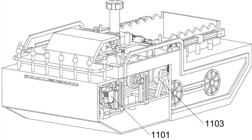
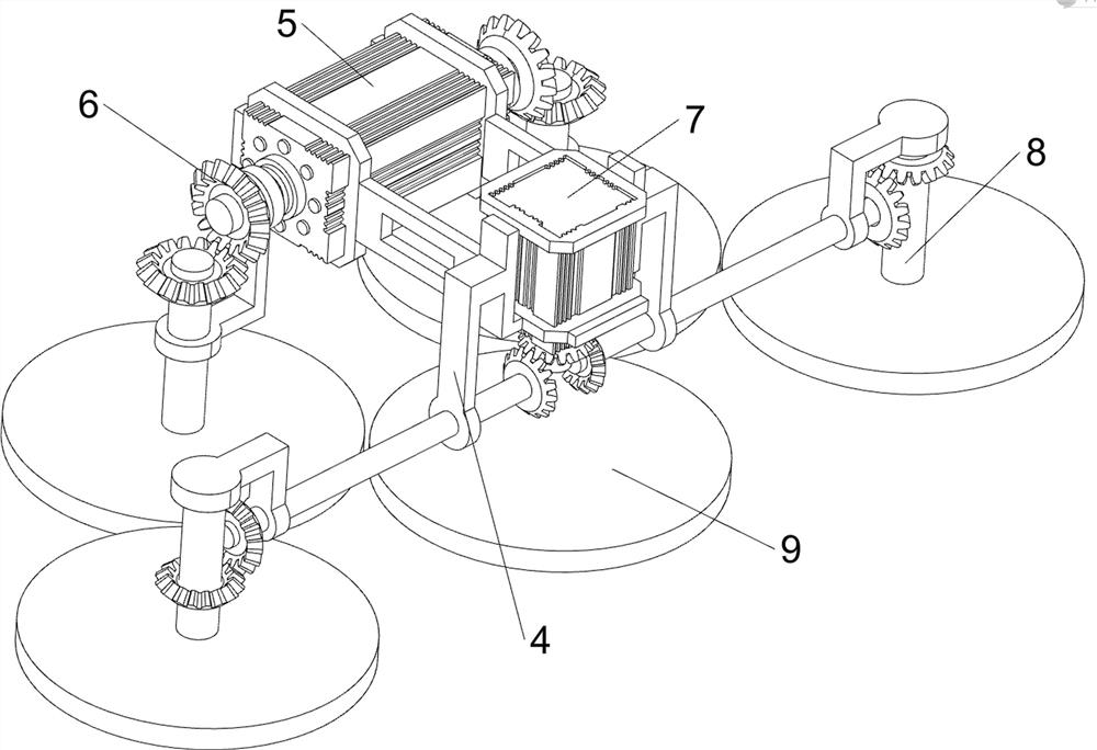
[0039] A mirror polishing equipment for electrical products, such as figure 1 , figure 2 , Figure 6 , Figure 7 , Figure 8 , Figure 9 , Figure 10 , Figure 11 and Figure 12 As shown, it includes a box body 1, a start key 2, a housing 4, a double-axis motor 5, a bevel gear 6, a servo motor 7, a first rotating shaft 8, a grinding wheel 9, a drive assembly 10, a rotation assembly 11 and a guide assembly 12 , the start key 2 is installed on the right front side of the upper part of the box body 1, the drive assembly 10 is arranged on the upper side of the inside of the box body 1, and the drive assembly 10 is slidably provided with a casing 4 connected to it, and a double shaft is installed on the left rear side of the casing 4. Motor 5, a servo motor 7 is installed in the middle of the right side of the inside of the housing 4, and the front and rear sides of the housing 4 are rotated to be provided with a rotating rod, and the left and right sides of the housing 4 a...

Embodiment 2

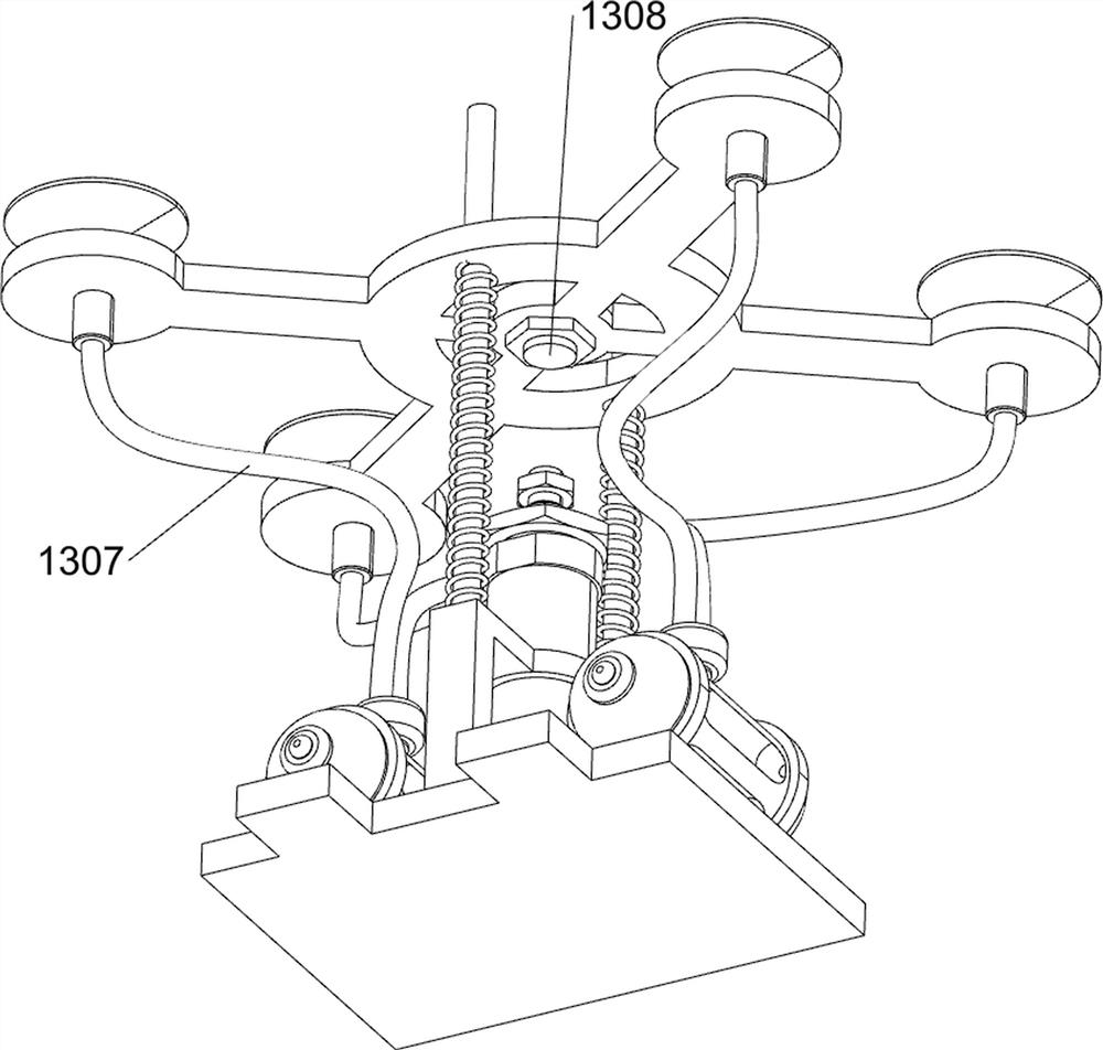
[0045] On the basis of Example 1, such as image 3 , Figure 4 , Figure 5 , Figure 13 , Figure 14 , Figure 15 , Figure 16 , Figure 17 and Figure 18 As shown, the adsorption assembly 13 is also included, and the adsorption assembly 13 includes a photoelectric sensor 1301, a second electric push rod 1302, a first connecting plate 1303, a suction cup 1304, a second spring 1305, a first air pump 1306, a first air pipe 1307 and A pressure sensor 1308, a photoelectric sensor 1301 is arranged symmetrically in the middle of the upper side inside the box body 1, a second electric push rod 1302 is installed between the lower right side inside the box body 1 and the support plate, and a sliding connection is made in the middle right side of the support plate. The first connecting plate 1303, the telescopic rod of the second electric push rod 1302 cooperates with the first connecting plate 1303, the top of the first connecting plate 1303 is evenly spaced with four suction cu...


PUM


Abstract

The invention relates to polishing equipment, in particular to mirror surface polishing equipment for an electrical product. The invention aims to provide the mirror surface polishing equipment for the electrical product, and the mirror surface polishing equipment is capable of automatically and intermittently feeding and has a guiding function. According to the technical scheme, the mirror surface polishing equipment for the electrical product comprises a box body, a start key, a driving assembly, a shell, a double-shaft motor and a servo motor; the start key is arranged on one side of the upper part of the box body; the driving assembly is arranged on the upper side in the box body; the shell is arranged on the driving assembly in a sliding manner; the double-shaft motor is arranged on one side of the interior of the shell; and the servo motor is arranged in the middle of the other side of the interior of the shell. After a first air pump is started, the first air pump sucks air on the surface of the glass into a first air pipe, the adsorption strength of a suction cup to the glass is improved, the glass can be stably polished, and the effects of adsorption and stability improvement are achieved.

Description

technical field [0001] The invention relates to a polishing device, in particular to a mirror polishing device for an electrical product. Background technique [0002] In terms of technical processing for electrical mirrors, the flat part of the production mold is strictly polished in order to produce a high-precision mirror effect. [0003] At present, in the traditional mirror grinding device, the grinding accuracy is low. During the grinding process, it is easy to shake and the stability is low. It is necessary to manually push the glass to the grinding block, and it does not have a guiding role. When it is easy to deviate from the position, the glass cannot be accurately pushed to the grinding block, resulting in low grinding efficiency of the glass, and also increasing people's labor intensity and workload. [0004] To sum up, it is necessary to design an automatic, intermittent feeding, and guiding mirror polishing equipment for electrical products to solve the above ...

Claims


Application Information

Patent Timeline
IPC IPC(8): B24B7/24B24B41/06B24B41/02B24B55/06B24B41/00
CPCB24B7/24B24B41/06B24B41/02B24B41/005B24B55/06B24B41/00Y02P70/10
Inventor 杨丽芳
Owner 深圳市科瑞德电器有限公司
Why Eureka
Try Eureka