Oil field fracturing flow-back fluid sewage purification treatment device

A sewage purification and oil field fracturing technology, which is applied in water/sewage treatment, water/sewage treatment equipment, water/sewage multi-stage treatment, etc., can solve the problems of reduced filtering effect, filter clogging, high concentration, etc., and achieve improvement Efficiency and effect, the effect of improving efficiency

Pending Publication Date: 2021-10-01
李瑞然
View PDF0 Cites 0 Cited by
  • Summary
  • Abstract
  • Description
  • Claims
  • Application Information

AI Technical Summary

Problems solved by technology

[0002] The pollutants in the flowback fluid generated during oilfield fracturing are complex in composition, high in concentration, high in viscosity, and difficult to treat, making it one of the more difficult sewage in oilfields. If it is not treated and discharged directly, it will seriously interfere with subsequent processes and seriously affect When it comes to oil field production, it leads to equipment blockage, environmental protection failure and many other problems. Generally, chemical oxidation, flocculation sedimentation and filtration treatment are used to deal with it. However, when the existing oil field fracturing flowback liquid sewage purification treatment device is filtering Due to the poor fluidity of the flowback liquid, incomplete oxidation and gel breaking, poor oil treatment effect and other factors, there are often more debris attached to the filter screen of the filter, and it will continue to increase, making the filtering effect continue to decrease. , eventually leading to filter clogging, affecting the final sewage treatment efficiency and treatment capacity, for this reason, the present invention proposes an oilfield fracturing flowback liquid sewage purification treatment device

Method used


Image

  • Oil field fracturing flow-back fluid sewage purification treatment device
  • Oil field fracturing flow-back fluid sewage purification treatment device
  • Oil field fracturing flow-back fluid sewage purification treatment device

Examples


Embodiment Construction

[0021] In order to make the techniques, creative features, objective and efficacy of the present invention, and the embodiments are further illustrated in connection with the specific embodiments.

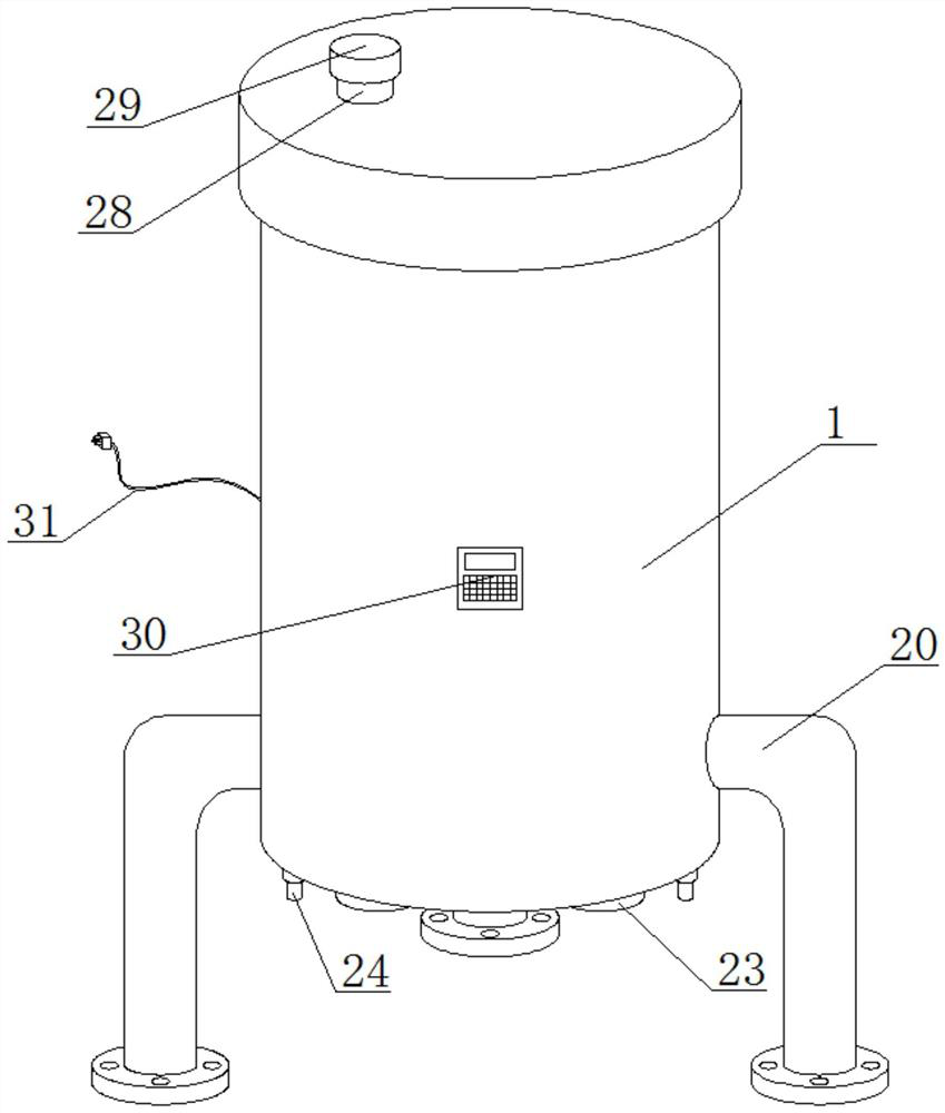
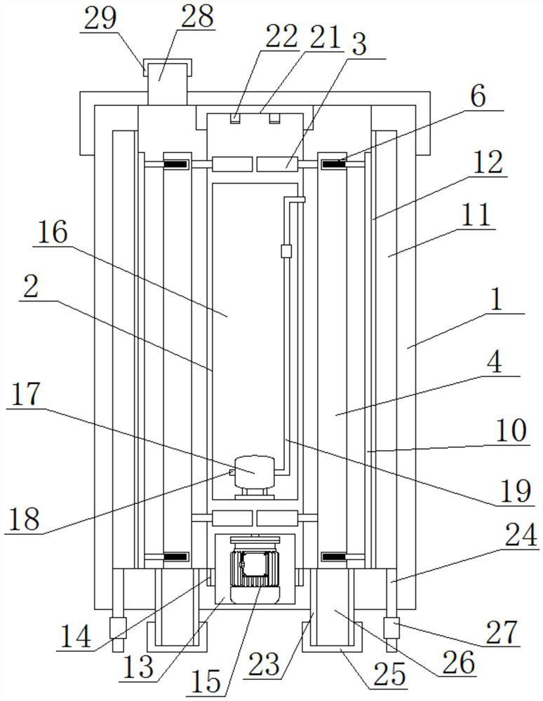
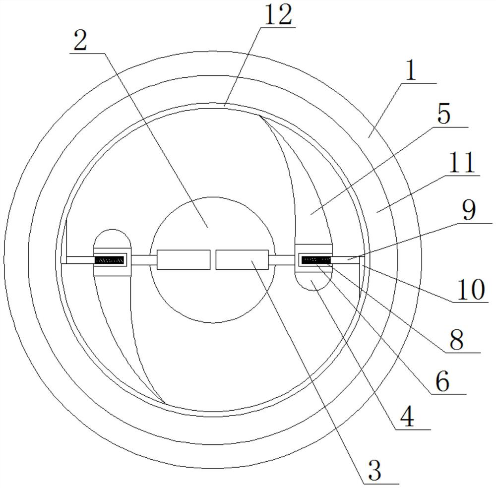
[0022] See Figure 1 to 5 The present invention provides a technical solution: an oil field fracturing returning drain sewage purification treatment device, including processing tank 1 and a central rotation shaft 2, and both sides of the central rotating shaft 2 are fixedly inlaid with electric push rod 3, said A round-side fixture 4 is fixedly mounted on the output shaft of the electric push rod 3, and the rear side of the rounded fixing seat 4 is fixedly mounted, and an arcuate elastic rubber pressure plate 5 is fixed, and one side of the rounded fixing seat 4 is fixed inlaid. The fixing rod 6 is opened at one end of the fixing rod 6, and the spring groove 7 is fixedly connected to the inner side wall of the opening, and one end of the telescoping rod 9 passes through the opening end...


PUM


Abstract

The invention provides an oil field fracturing flow-back fluid sewage purification treatment device, and the device comprises a treatment tank and a center rotating shaft; electric push rods are fixedly embedded in the two sides of the center rotating shaft correspondingly, and round edge fixing seats are fixedly installed on output shafts of the electric push rods. The device is reasonable in design; a round-edge fixed seat is mounted on a central rotating shaft in a treatment tank through an electric push rod, an arc-shaped elastic rubber pressing plate and an arc-shaped scraper with certain flexibility are mounted on the round-edge fixing seat, and when the central rotating shaft rotates clockwise, the arc-shaped scraper firstly scrapes off attachments on the inner wall of a filter cartridge; then the arc-shaped elastic rubber pressing plate extrudes the flow-back liquid between the arc-shaped elastic rubber pressing plate and the filter cartridge, and water is extruded to penetrate through the filter cartridge and enter the annular water tank, so the flow-back liquid can be filtered efficiently all the time, the filtering efficiency and effect can be effectively improved, and the sewage purification treatment efficiency of the flow-back liquid is further improved.

Description

Technical field [0001] The present invention belongs to the technical field of oilfield fracturing return drainage treatment equipment, and in particular, the present invention relates to an oil field fracturing return drain sewage purification treatment device. Background technique [0002] The returning liquid contaminant components produced during the fracturing process of oilfield, high concentration, high viscosity, difficulty in treatment, so that one of sewage treated with more difficult oil fields, if not dealing with direct discharge, will seriously interfere with subsequent processes, seriously affected To oil field production, the equipment is blocked, environmentally friendly, etc., generally used chemical oxidation, flocculation precipitation and filtration process for treatment, however, the existing oilfield fracturing return drain sewage purification treatment device is filtered, Since the fluidity of the return solution is poor, the oxidation is not thorough, the...

Claims


Application Information

Patent Timeline
Patent Type & Authority Applications(China)
IPC IPC(8): C02F9/04C02F103/10
CPCC02F1/00C02F1/001C02F2103/10C02F2201/002C02F2201/004C02F2201/005C02F2301/066C02F2303/16C02F2303/14
Inventor 李瑞然
Owner 李瑞然
Why Eureka
Try Eureka