
45MW ultrahigh-pressure reaction type backpressure steam turbine

A back-pressure steam turbine and reactionary technology, applied in the direction of engine components, machines/engines, mechanical equipment, etc., can solve the problems of low unit cycle efficiency, large pollution emissions, low energy utilization rate, etc., to avoid low energy utilization rate , high cycle efficiency, and the effect of shortening the length of the unit

Pending Publication Date: 2021-10-01
HARBIN TURBINE
View PDF0 Cites 1 Cited by
  • Summary
  • Abstract
  • Description
  • Claims
  • Application Information

AI Technical Summary

Problems solved by technology

[0007] In order to solve the problems of low main steam parameters, high cost, low unit cycle efficiency, high power supply coal consumption, low energy utilization rate and large pollution discharge in the existing back pressure steam turbine, the present invention proposes a 45MW ultra-high pressure reaction back pressure steam turbine

Method used


Image

  • 45MW ultrahigh-pressure reaction type backpressure steam turbine
  • 45MW ultrahigh-pressure reaction type backpressure steam turbine
  • 45MW ultrahigh-pressure reaction type backpressure steam turbine

Examples


specific Embodiment approach 1

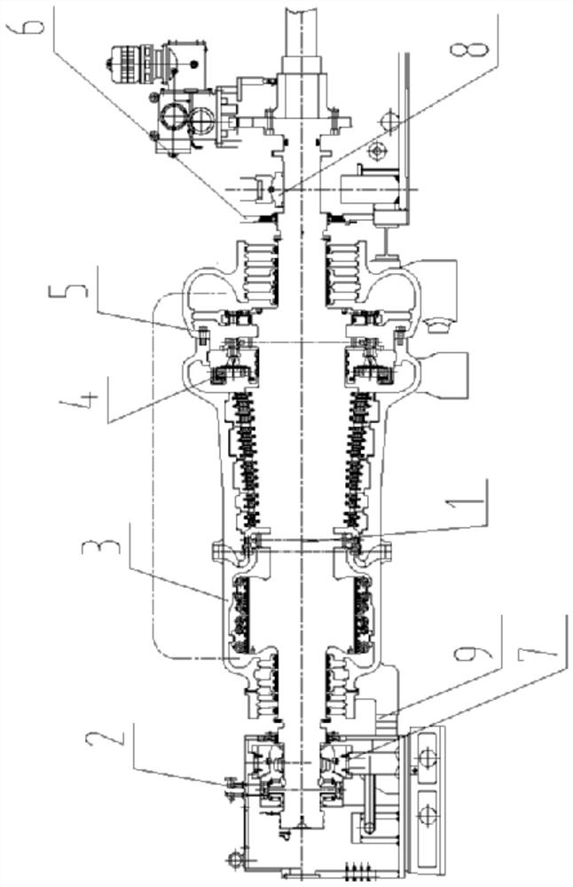
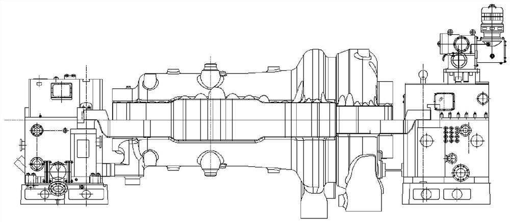
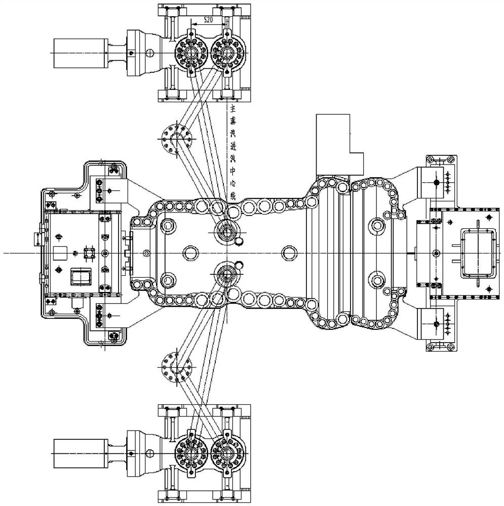
[0023] Specific implementation mode one: combine Figure 1 to Figure 5 To illustrate this embodiment, a 45MW ultra-high pressure reactionary backpressure steam turbine described in this embodiment includes a rotor 1, a front bearing housing 2, a cylinder front 3, a rotary partition 4, a cylinder rear 5 and a rear bearing housing 6;

[0024] One end of the rotor 1 is inserted into the side through hole of the front bearing box 2, and the rotor 1 is rotationally connected with the front bearing box 2, and the other end of the rotor 1 passes through the front part 3 of the cylinder and the rear part 5 of the cylinder in turn, and then is inserted into the rear bearing In the side through hole of the box 6, and the rotor 1 is rotationally connected with the rear bearing box 6, and a rotary partition 4 is provided between the inner wall of the rear part 5 of the cylinder and the outer wall of the rotor 1;

[0025] In this specific embodiment, when in use, the rear bearing box 6 is ...

specific Embodiment approach 2

[0028] Specific implementation mode two: combination figure 1 Describe this embodiment, this embodiment is a further limitation on the steam turbine described in Embodiment 1, a 45MW ultra-high pressure reaction back pressure steam turbine described in this embodiment, the side of the front bearing box 2 is through A front bearing 7 is embedded in the hole, and one end of the rotor 1 is fixedly connected with the inner ring of the front bearing 7 .

specific Embodiment approach 3

[0029] Specific implementation mode three: combination figure 1 Describe this embodiment. This embodiment is a further limitation of the steam turbine described in Embodiment 1. For a 45MW ultra-high pressure reactionary backpressure steam turbine described in this embodiment, the side of the rear bearing housing 6 is through A rear bearing 8 is embedded in the hole, and the other end of the rotor 1 is fixedly connected with the inner ring of the rear bearing 8 .


PUM


Abstract

The invention discloses a 45MW ultrahigh-pressure reaction type backpressure steam turbine, and relates to the field of steam turbines. The problems that an existing backpressure steam turbine is low in main steam parameter, high in cost, low in unit circulation efficiency, high in power supply coal consumption, low in energy utilization rate and large in pollution discharge amount are solved. One end of a rotor is inserted into a side face through hole of a front bearing box, the rotor is rotatably connected with the front bearing box, the other end of the rotor sequentially penetrates through the front portion and the rear portion of an air cylinder and then is inserted into a side face through hole of a rear bearing box, the rotor is rotatably connected with the rear bearing box, and a rotary partition plate is arranged between the inner wall of the rear portion of the air cylinder and the outer wall of the rotor. The invention belongs to the field of steam turbines.

Description

technical field [0001] The invention relates to the field of steam turbines, in particular to a 45MW ultra-high pressure reaction back pressure steam turbine. Background technique [0002] The steam turbine is a kind of turbomachinery used to convert the heat energy of the gas into the mechanical work. A steam turbine is a heat turbine that uses steam as a working medium and converts the thermal energy of steam into mechanical work; [0003] Electricity is the main driving force of modern production and an important condition for improving people's material and cultural life. Electricity consumption has become one of the important symbols to measure the level of a country's technological and economic development. The power industry is an industry that converts energy resources into electricity, and its development marks the degree of development of a country. At present, the main uses of steam turbines are as follows. [0004] The first use is thermal power generation. T...

Claims


Application Information

Patent Timeline
Patent Type & Authority Applications(China)
IPC IPC(8): F01D25/24F01D25/16
CPCF01D25/24F01D25/16
Inventor 王铮鲍大虎张立志张晨旭邹婉秋刘扬黄智敏姜喜星
Owner HARBIN TURBINE
Learn More