
Rotor compressor in side plug wiring mode

A rotor compressor and a compressor technology, which are applied in the field of rotor compressors, can solve the problems of limited installation space of the compressor cabin, unfavorable control of the axial space of the compressor, unfavorable design of refrigeration appliances, etc., so as to reduce the processing cost. , Conducive to the simple and convenient effect of space setting, installation and pipe placement

Pending Publication Date: 2021-10-01
黄石东贝压缩机有限公司
View PDF11 Cites 0 Cited by
  • Summary
  • Abstract
  • Description
  • Claims
  • Application Information

AI Technical Summary

Problems solved by technology

This conventional method is applied to various rotor models, and the rotor machine is applied to various refrigeration appliances. This structure must have enough space for the installation space in the conventional refrigeration appliance cabinet to ensure the discharge on the upper cover. There is installation space for the pipe and the external pipe, and a protective cover is installed on the terminal post of the upper cover, which will also occupy a certain space. With the improvement of people's living standards, various electrical facilities are developing rapidly, and some refrigeration appliances are miniaturized. In this way, the installation space of the compressor cabin is limited. Since most of the rotor compressors adopt a vertical structure, especially the position of the upper cover of the compressor, the space is too small, which is not conducive to the design of refrigeration appliances. Currently on the market There have been many occasions that there is a higher requirement for the height of the rotary compressor, and the height of the rotary compressor is required to be small to facilitate installation and pipeline placement.
[0003] For example, the Chinese utility model patent (publication number: CN209100228U) disclosed a compressor upper case cover and a micro compressor including it in 2019. The compressor upper case cover includes a sealing terminal structure and a L type upper exhaust elbow; the upper exhaust elbow includes a contact portion and a bent portion communicating with the exhaust port on the upper case cover; the utility model sets the exhaust pipe into an elbow form, so that The space above the upper cover can be reduced, but there are still many components on the entire upper cover, and the upper cover is more complicated, which is not conducive to the control of the overall axial space of the compressor

Method used


Image

  • Rotor compressor in side plug wiring mode
  • Rotor compressor in side plug wiring mode
  • Rotor compressor in side plug wiring mode

Examples


Embodiment 1

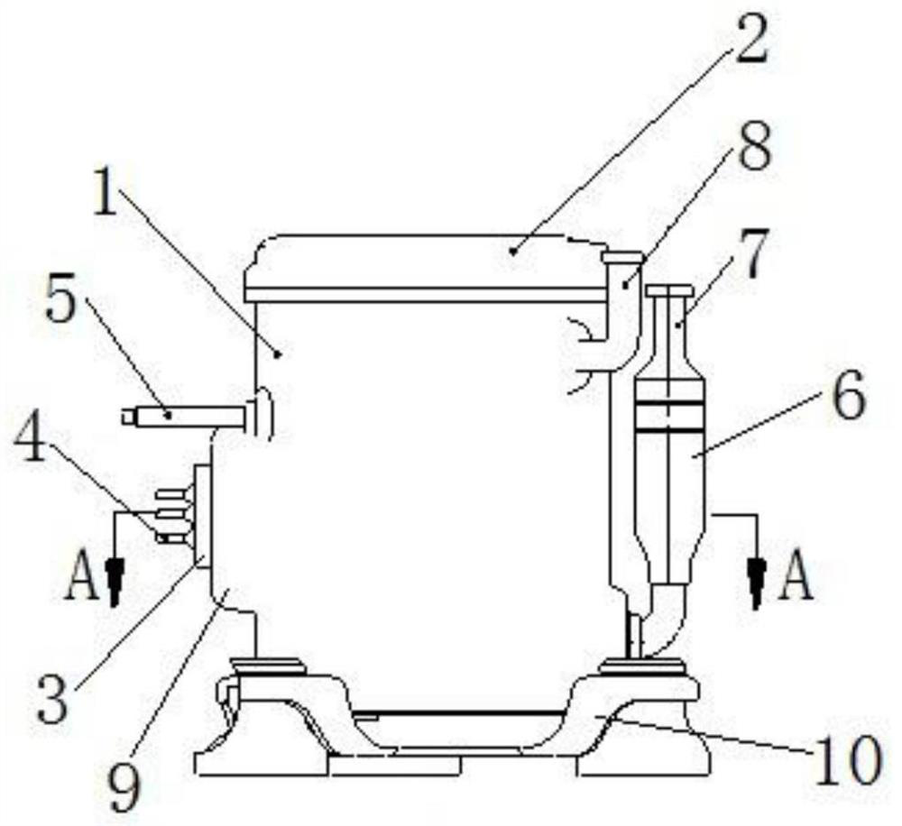
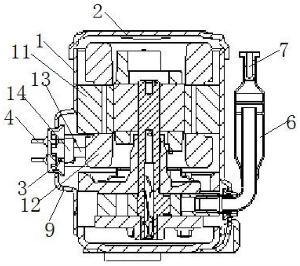
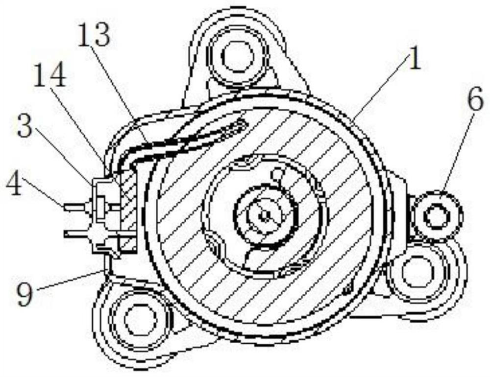
[0035] Such as Figure 1 to Figure 4 As shown, a rotary compressor in the form of side plug-in wires includes a compressor cylinder 1, an upper cover 2 is provided on the compressor cylinder 1, and a liquid accumulator is connected to the outer peripheral side of the compressor cylinder 1. 6. The compressor barrel 1 is provided with a motor, the upper cover 2 is a complete end cover without holes, and the outer peripheral side of the compressor barrel 1 is provided with a protruding cover 3, the cover There are several terminal posts 4 inside the body 3, one end of the terminal post 4 protrudes from the cover body 3, and the other end is connected to the lead wire 13 of the motor through a terminal block 14; the outer circumference of the compressor barrel 1 is also connected to There is an exhaust pipe 8 communicating with the interior, and the exhaust pipe 8 and the exposed part of the terminal post 4 all rotate around the central axis of the compressor barrel 1 at the large...

Embodiment 2

[0054] This embodiment provides a lead wire method for a rotary compressor.

[0055] A wiring method for a rotor compressor, comprising the following steps: After the motor is installed, lead the motor lead wires from the wire package 12 at the lower end of the stator core 11 of the motor, and then connect the lead wires 13 to the junction block 14 connection, the terminal block 14 is fixed and separates different leads, and then connected to different terminals 4, after the connection is completed, the cover body 3 is fixed at the opening to complete the package.


PUM


Abstract

The invention discloses a rotor compressor in a side plug wiring mode. The rotor compressor comprises a compressor cylinder, an upper cover and a liquid storage device. The upper cover is a hole-free type complete end cover, a protruding cover body is arranged on the peripheral side of the compressor cylinder, a plurality of binding posts are arranged in the cover body, and the binding posts are arranged in the compressor cylinder. One ends of the binding posts extend out of the cover body, and the other ends are connected with a lead of a motor through a wiring block. The periphery of the compressor cylinder is further connected with an exhaust pipe communicating with the interior of the compressor cylinder. The exhaust pipe and the exposed parts of the binding posts are both within the radius range of rotation around the central axis of the compressor cylinder at the maximum outer contour of the liquid storage device. According to the side plug wiring mode of the rotor compressor, the axial height of the rotor compressor can be greatly simplified, the height above the upper cover is saved, installation of the rotor compressor and pipeline placement are easy and convenient, the space utilization rate is higher, space arrangement of a refrigeration appliance is facilitated, and the volume utilization rate of the refrigeration appliance is improved.

Description

technical field [0001] The invention relates to the technical field of rotary compressors, in particular to a rotary compressor in the form of side plug-in wires. Background technique [0002] In the structure of the rotor compressor, the existing technology is to weld the terminal post through the hole of the upper cover, connect the motor lead wire to the external power supply, weld the exhaust pipe through the hole in the upper cover, connect the gas in the shell with the external pipe, and connect the terminal post And the exhaust pipe, the fixed screw is welded on the upper cover. The lead wires of the motor inside the casing are connected to the three terminal posts welded on the upper cover through the terminal block to ensure that the external power supply communicates with the motor. This conventional method is applied to various rotor models, and the rotor machine is applied to various refrigeration appliances. This structure must have enough space for the install...

Claims


Application Information

Patent Timeline
Patent Type & Authority Applications(China)
IPC IPC(8): F04C27/00F04C29/00F04C29/12H02K5/22
CPCF04C29/00F04C27/00F04C29/12H02K5/225
Inventor 戴竟雄王永昌李华军甘念
Owner 黄石东贝压缩机有限公司
Learn More